Cable Connections
Installation Handbook, Autroprime Interactive Fire Detection System, 116-P-APRIME2-INSTAL/DGB, Rev. C, 2016-29-02,
Autronica Fire and Security AS
Page 51
9.12.4 Connections for Panel Bus
7 6 5 4 3 2 1 7 6 5 4 3 2 1
Inst
Gnd
B2 A2 0V + 0V +
Inst
Gnd
B1 A1 0V + 0V +
24V- 2 24V- 1 24V- 2 24V- 1
BU/BV Mimic Panel Bus IN J5 BU/BV Mimic Panel Bus OUT J4
9.12.5 Connections for Slave Panels
Out 1 Out 2 RS-485 Inst.
+24V 0V +24V 0V A3 B3 A4 B4 Gnd.
9 8 7 6 5 4 3 2 1
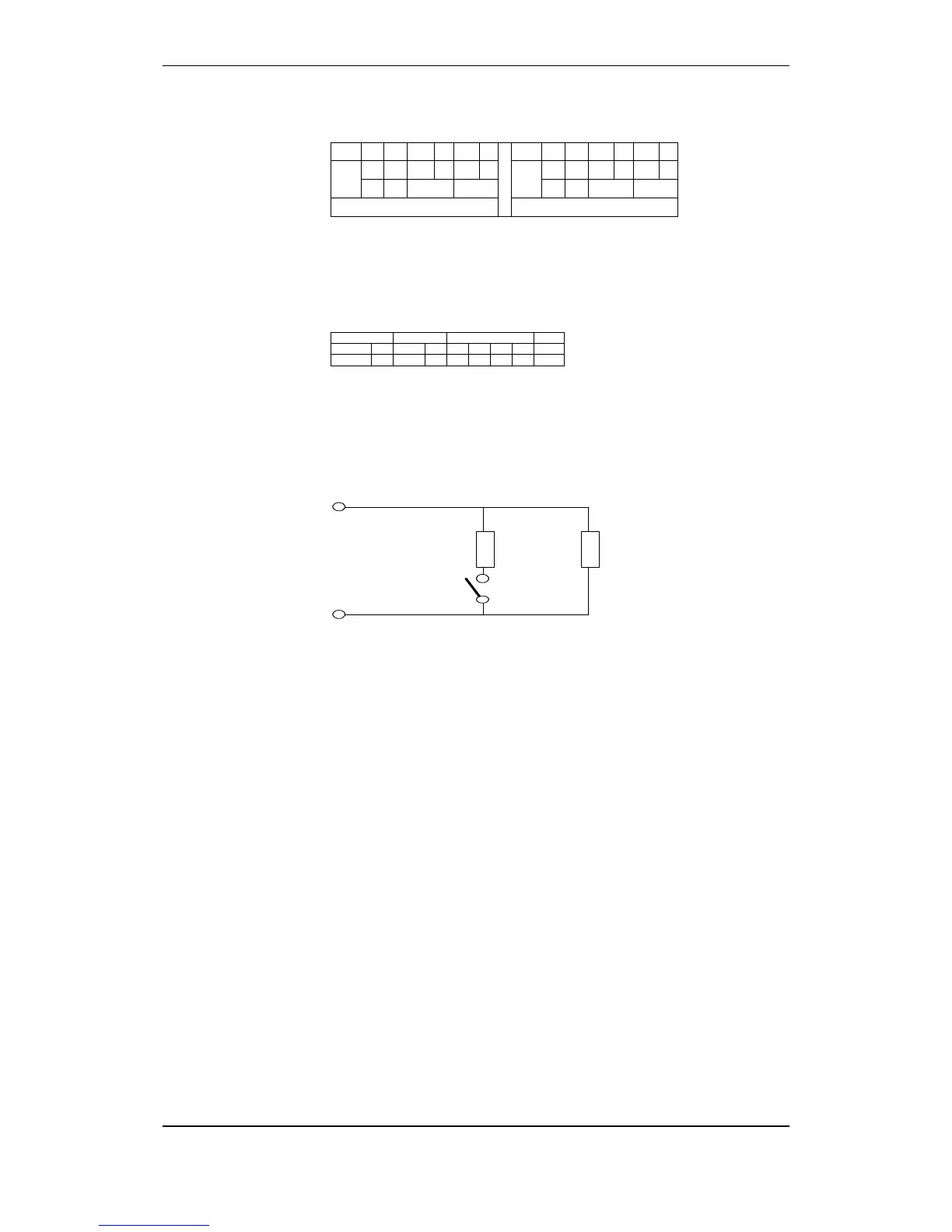
9.12.6 Terminals for monitored inputs
End resistor
2 kohm
Resistor 910 ohm
A ctivation
switch
Input +
Input -

 Loading...