Cable Connections
Installation Handbook, Autroprime Interactive Fire Detection System, 116-P-APRIME2-INSTAL/DGB, Rev. C, 2016-29-02,
Autronica Fire and Security AS
Page 46
9.10 Panel Bus Connections to BU-, BV- and BS-panels
CAUTION
Note that when connecting additional panels on a panel bus, the
communication cables inside the cabinet (Fire Alarm Control
Panel) must be connected as shown in chapter 9.9.2.
If additional panels are to be connected to the RS-485 Panel Bus,
the ad ditional panel’s Panel Bus connector J13 and J14 is used.
This connector is located on the rear side of the BU-, BV- and BS-
panels.
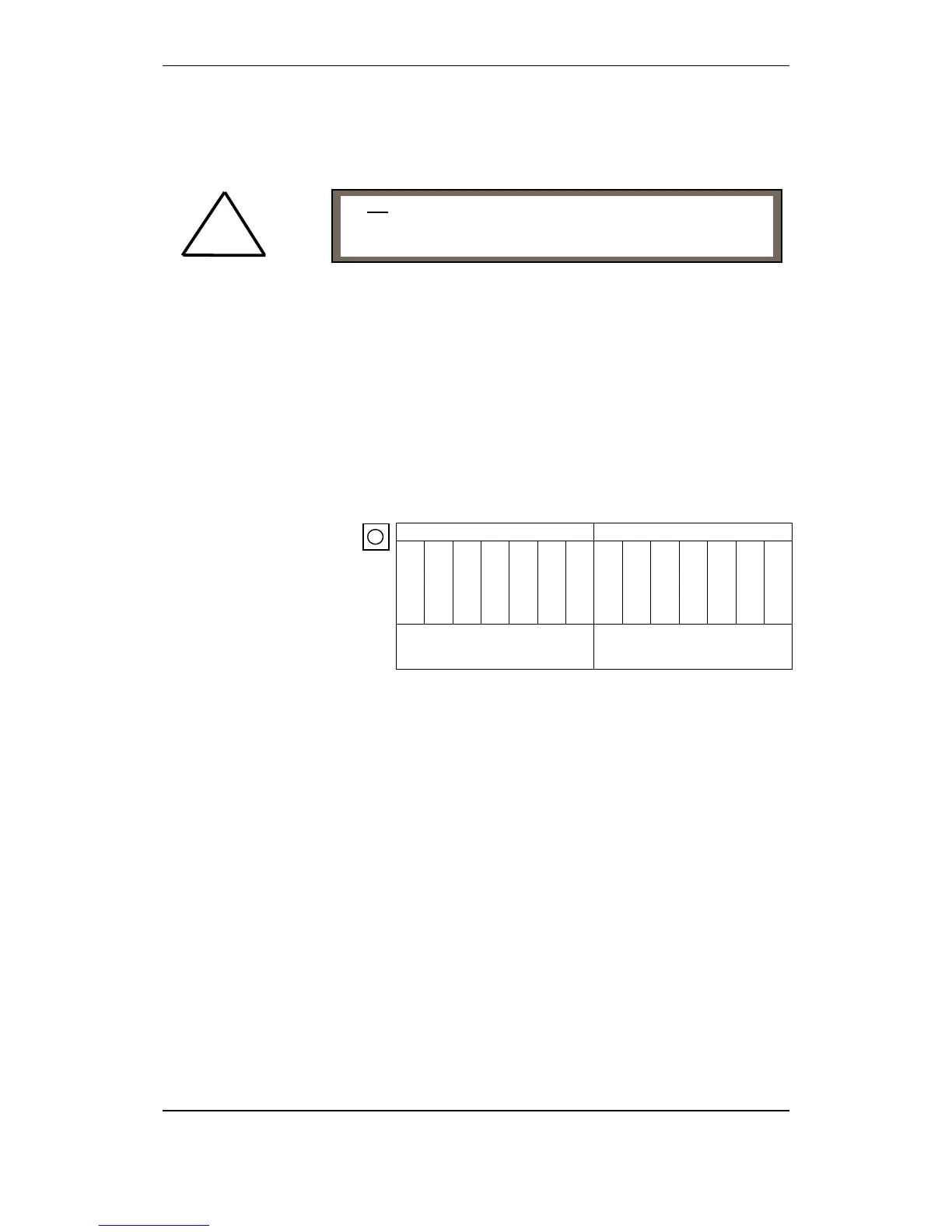
Panel Bus connector on additional panels (viewed from rear side of
panel where cables are to be connected)
J14 J13
24ViN1
0V iN 1
24ViN2
0v iN 2
A1_1
B1_1
GND
24ViN1
0V iN 1
24ViN2
0v iN 2
A2_2
B2_2
GND
Panel Bus In Panel Bus Out
Do not connect the 24V wire to the terminal points used for
communication (A and B terminals). This will lead to
malfunction of the communication circuits.
!

 Loading...