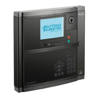
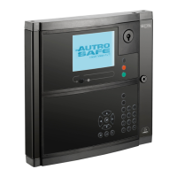
Addressing Panels
Installation Handbook, Autroprime Interactive Fire Detection System, 116-P-APRIME2-INSTAL/DGB, Rev. C, 2016-29-02,
Autronica Fire and Security AS
Page 15
6. Addressing Panels
6.1 Rotary Switch on Panels
All Autroprime panels (BS-200, BS-200M, BS-200L, BS-211, BU-
210, BV-210) must be assigned addresses by means of the rotary
switch located on the rear side of the panel. The addresses must
be set before mounting.
6.2 Addressing the Fire Alarm Control Panel (BS-200)
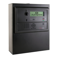
The main Fire Alarm Control Panel (BS-200, BS-200L, BS-200M)
with the integrated Operator Panel BS-210 must always have
address 0 (the arrow pointing straight downwards). Address 0 is
preset from the factory.
Note that only 1 Operator Panel BS-210 (either as an integrated
part of Fire Alarm Control Panel BS-200 or as a separate panel
mounted outside a cabinet) can be connected to the panel bus.
6.3 Addressing other Panels
All other panels connected to the RS-485 Panel Bus, including
Repeater Panel BS-211, Fire Brigade Panel BU-210, Information
Panel BV-210 and “Larmlagringspanel BU-211” have addresses
from 1-9.
6.4 Addressing Mimic Drivers
To address the Mimic Drivers the X2 Panel Bus Address Switch is
used. If S2.7 is set to Master, X2 sets the panel bus address. If
S2.7 is set as slave, X2 sets the RS-485 daisy-chain slave
address. The range for the switch is 1-9.
 Loading...
