Cable Connections
Installation Handbook, Autroprime Interactive Fire Detection System, 116-P-APRIME2-INSTAL/DGB, Rev. C, 2016-29-02,
Autronica Fire and Security AS
Page 39
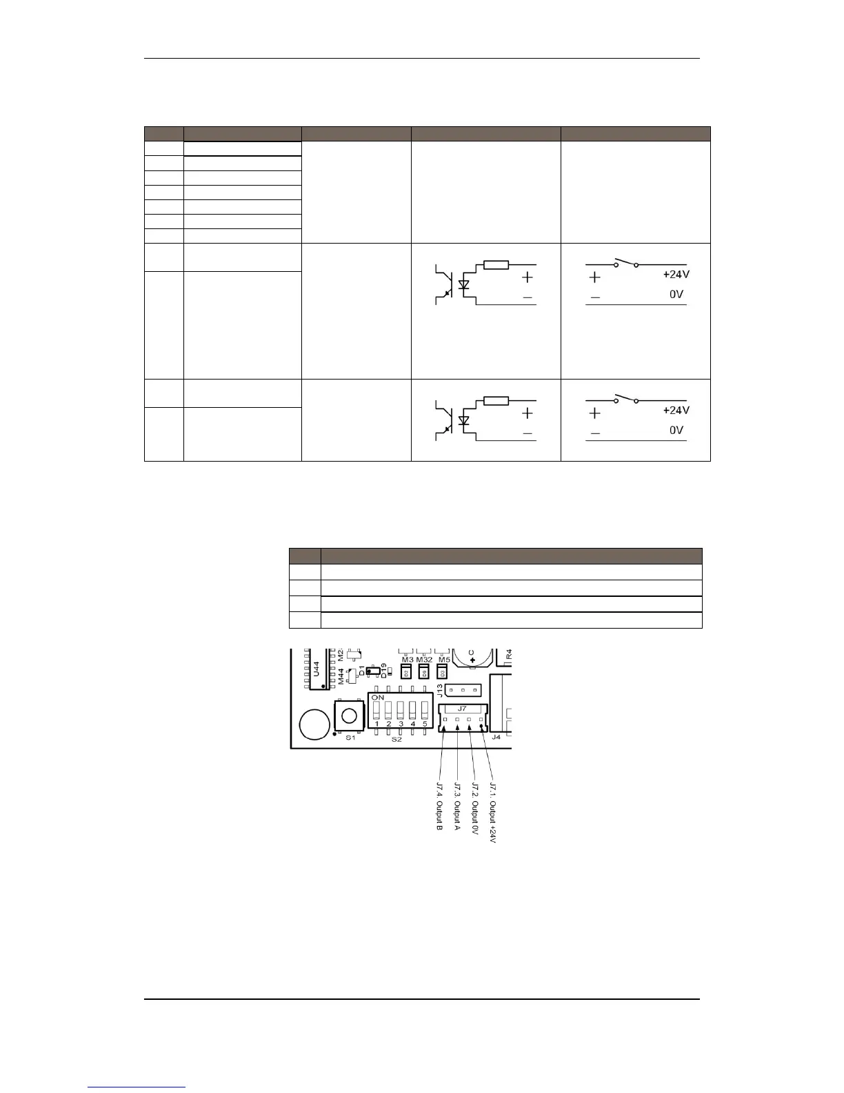
9.8.6 Auxiliary Terminal Block J6
J6- Description Internal External
1 RS-232 TX
External Interface
Optional data lines
2 RS-232 RX
3 RS-232/422/485 0V
4 RS-422/485 A
5 RS-422/485 B
6 RS-422/485 Z
7 RS-422/485 X
8
Non-monitored Input
1 +
User configurable
input
Activates on
closing contacts
between 24VDC
and 0V.
Observe polarity
9
Non-monitored Input
1 -
10
Non-monitored Input
2 +
User configurable
input
Activates at
application of
24VDC.
Observe polarity
11
Non-monitored Input
2 -
9.8.7 Operator Panel, Standalone, J7
J7- Description
1 Operator Panel Output +24V
2 Operator Panel Output 0V
3 Operator Panel Output A
4 Operator Panel Output B
8
9
10
11

 Loading...