Home
Autronica
Fire Alarms
Autroprime
Autronica Autroprime Installation Handbook
4
of 1
of 1 rating
86 pages
Give review
Manual
Specs
To Next Page
To Next Page
To Previous Page
To Previous Page
Loading...
Maritime Installations
Installation Handbook, Autroprime
Interactive Fire Detection System, 116-P-
APRIME2-INSTAL/DGB,
Rev. C, 2016-29-02,
Autronica Fire and Security AS
Page 58
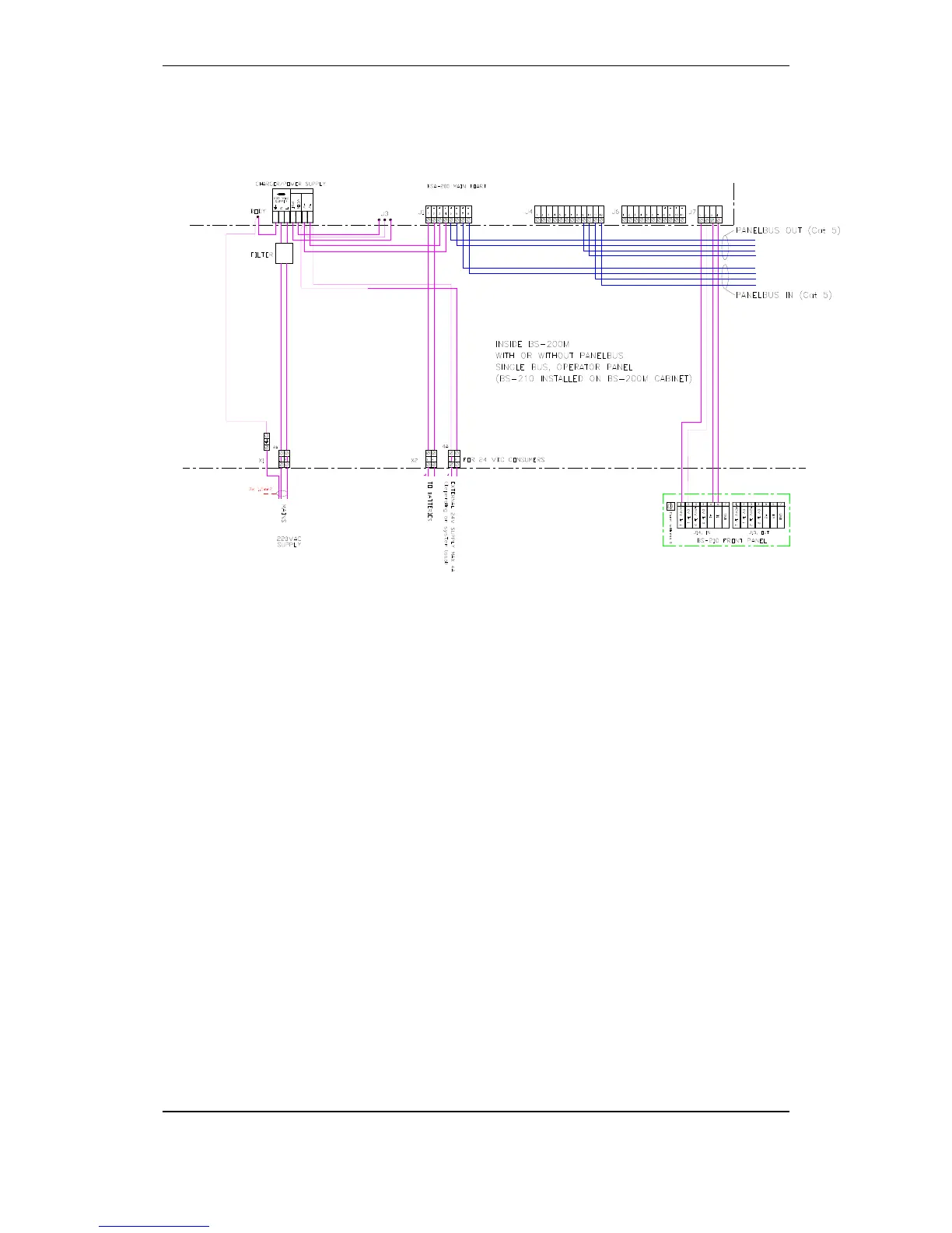
10.2.3.4
Cabinet with integrated BS-210 with/without external
panel bus – without mains changeover relay
57
59
Table of Contents
Default Chapter
3
Table of Contents
3
1 Introduction
7
About the Handbook
7
The Reader
7
Reference Documentation
7
2 Pre-Installation
8
Location
8
Environmental Requirements
8
Mounting Height / Space Requirement
8
Mounting Alternatives
8
3 Panels, Brackets and Cabinet
9
4 Interconnecting Panels on the Panel Bus
11
Overview
11
5 Mounting Instructions
12
6 Addressing Panels
15
Rotary Switch on Panels
15
Addressing the Fire Alarm Control Panel (BS-200)
15
Addressing Other Panels
15
Addressing MIMIC Drivers
15
7 Mounting Drawings
16
Hole Dimensions - Mounting Bracket for BS-210 and BS-211
16
Hole Dimensions - Mounting Bracket for BU-210, BU-211 and BV-210
17
8 Cable Specifications
18
Calculating the Current Consumption
18
Tables
18
Onboard I/O and Power
19
Panel Bus and Serial Port
20
Detection Loop Cables
20
The Panel Bus Cable Requirements
21
Characteristic Impedance and Signal Attenuation
21
High-Voltage and Noisy Environments
21
Cable Length and Power Consumption
22
Calculation of Power Consumption and Cable Loss
24
Power Supply and Battery Capacity
24
9 Cable Connections
25
Cabling - Overview
25
Overview Internal Cable Layout
27
Battery Connections
28
Connections to Power Supply / Mains Power
30
Fuses
31
Connection of External DC Power
32
Terminal Points Overview - Main Board
33
Description of Terminal Points - Main Board
34
Main Terminal Block J1
34
Ethernet RJ45 Connector J2
37
Power Supply Control and Battery Temperature Measurement J3
37
Auxiliary Term Inal Block J4
38
Add-On Network Interface, J5
38
Auxiliary Terminal Block J6
39
Operator Panel, Standalone, J7
39
Add-On Looper Interface J8
40
USB Host J10
40
User Configurable Inputs
40
User Configurable Outputs
41
Cable Connections Inside the Cabinet (Fire Alarm Control Panel)
42
Connections (J7) for a Standalone Cabinet with Integrated BS-210
42
Connections (J4) for a Cabinet with External BS-210 and no External Panel Bus
43
Connections (J4) for a Cabinet with Integrated BS-210 and External Panel Bus
44
Connections (J4) for a Cabinet with External BS-210 and External Panel Bus
45
Panel Bus Connections to BU-, BV- and BS-Panels
46
Overview Panel Bus
47
Connections to MIMIC Drivers (BUR-200)
48
Terminal Points - Overview
49
Switch Settings
50
Connection of Master and Slave MIMIC Drivers
50
Connections for Panel Bus
51
Connections for Slave Panels
51
Terminals for Monitored Inputs
51
Ground Fault
52
10 Maritime Installations
53
Typical Maritime Installation - Overview
53
Fire Alarm Control Panel BS-200M
54
External Connections
54
Detection Loop Connections - Extended Terminal Block
55
Internal Wiring
56
Panel Bus Connection
59
MIMIC Cabinet BUR-200
60
External Battery Cabinet
61
Dimensions
61
Internal Connections in Battery Cabinet
63
11 Startup
64
Power up
64
12 Switches and Indicators on the Main Board
66
Overview
66
Reset Switch (S1)
66
Dip-Switches for Mode Settings (S2)
67
Battery Short-Circuit Protection
67
Battery Restart after Deep Discharge (S3)
68
Serial Port Settings (S4)
69
System Fault LED Indicator (Yellow)
69
Status LED Indicator (Red)
69
Power LED Indicator (Green)
69
Regulated 24V Indicator (Green)
69
13 Exporting / Importing Configuration Data
70
USB Output
70
Entering the Service Menu
71
Exporting Configuration Data
73
Importing Configuration Data
73
Backup Current Configuration
74
Select Configuration & Restart System
74
Save Configuration
75
14 Changes on the Detection Loop
76
Typical Scenarios
76
Remove a Unit and Insert the same Unit
76
Remove a Unit and Insert Another Unit of the same Type
77
Remove a Unit and Insert Another Unit of a Different Type
77
Add a New Unit to the Detection Loop
78
Remove a Loop Unit from the Detection Loop
78
Major Changes / Clear Loop Config. - Restart System
79
15 Changes on the Panel Bus
80
Typical Scenarios
80
Adding an Extra Panel to the Panel Bus
80
Removing a Panel from the Panel Bus
81
Replacing a Panel of the same Type and with the same Address
81
Replacing a Panel of the same Type but with a Different Address
82
Replacing a Panel of a Different Type
82
16 Appendix
83
Text Foils
83
Other manuals for Autronica Autroprime
Operator's Handbook
82 pages
Connecting
38 pages
4
Based on 1 rating
Ask a question
Give review
Questions and Answers:
Need help?
Do you have a question about the Autronica Autroprime and is the answer not in the manual?
Ask a question
Autronica Autroprime Specifications
General
Brand
Autronica
Model
Autroprime
Category
Fire Alarms
Language
English
Related product manuals
AUTROSAFE Self Verify BS-310
3 pages
AutroGuard Multicriteria Protector V-430 Series
126 pages
Autronica Autroprime 2
152 pages
Autronica Autroprime BS-200
30 pages
Autronica Autroprime BS-200M
30 pages
Autronica BS-420
159 pages
Autronica BS-310
133 pages
Autronica BS-430
159 pages
Autronica AutroSafe
93 pages
Autronica AutroSafe BSD-340
27 pages