Setting RFID Options 8-1
SETTING RFID OPTIONS
The RFID printer has been engineered to encode (program) an RFID (Radio
Frequency Identification) inlay while printing. RFID inlays contain an embedded
programmable microchip and an antenna.
The printer supports EPC Class-1 Generation-2 UHF (C1Gen2) protocol encoding
following the EPC™ Radio-Frequency Identity Protocols Class 1 Generation 2 UHF RFID
Protocol for Communications at 860-960MHz Standards (GS1 EPCglobal™ Specification
for RFID Air Interface).
A printer with RFID can also print standard (non-RFID) supplies. Do not use skip index
with RFID supplies.
To create a format with an RFID data field and program RFID data, refer to the Packet
Reference Manual.
RFID Operational Overview
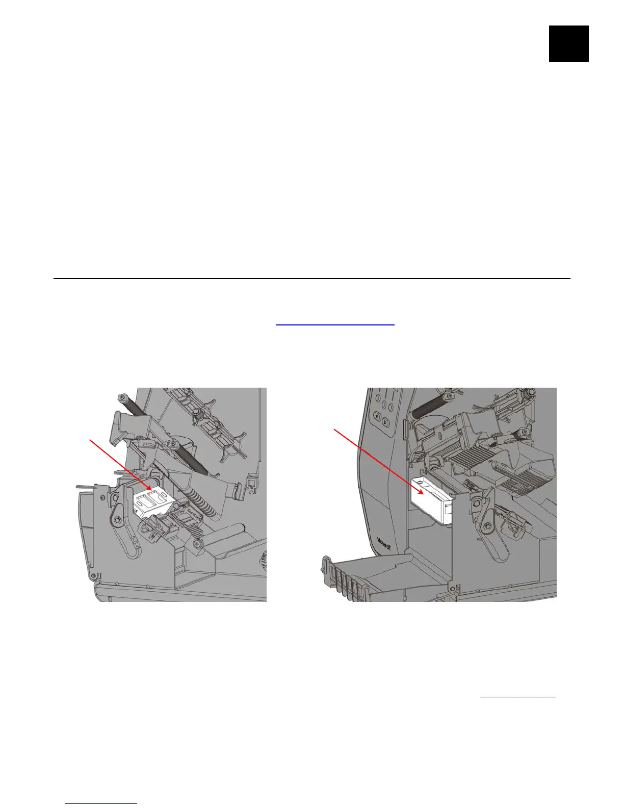
An RFID printer has an antenna to program RFID inlays. Two antenna modules are
available – one for FCC and one for ETSI frequencies. The antenna module type prints
on the RFID configuration label. See “Printing a Test Label
” for more information.
An optional external verifier (reader) is available to verify the data within a programmed
RFID inlay. The antenna is located within the supply path. The optional external verifier
is located where the supply exits the printer.
Note: Peel mode or liner take-up is not available with optional external RFID verifier.
The RFID printer operates in one of two modes:
♦ non-stop encode mode
In non-stop encode mode, the printer does not pause (or
stop) while encoding the RFID inlay. Non-stop encode is
useful with minimum “pitch” supplies. See “What is Pitch
”
for more information.
♦ stop-to-encode mode
In stop-to-encode mode, the printer pauses (or stops)
while encoding the RFID inlay.
External