EasyManua.ls Logo

BADU OmniTronic - Terminal Connections and Diagrams

BADU OmniTronic
Print Icon
To Next Page IconTo Next Page
To Previous Page IconTo Previous Page
Loading...
Installation
03|2022 EN 43
Contact load
Z1, Z2 maximum 2 A, 250 V~ AC3
11, 12, 14 maximum 2 A, 250 V~ AC3
Connection load
Lp, Np maximum 4 A, 250 V~ AC3
Rocker switch
The rocker switch installed on the front turns the whole device on
and off.
The light on the rocker switch displays the operational readiness.
If the device is turned off, no contact information can be output via
Z1-Z2.
5.3.1 Replacing the fuses
There are two different fuses present.
4 A fuse for pumps with asynchronous motors
315 mA to safeguard the control unit’s circuit board
Pos: 47.20 /Tec hnische Dok umentation Sp eck Pumpen/B etriebsanleitung/ Installation/El ektrischer A nschluss/BADU Omnitronic/Klemmenplan @ 12\mo d_152569614 8798_370.docx @ 180987 @ 3 @ 1
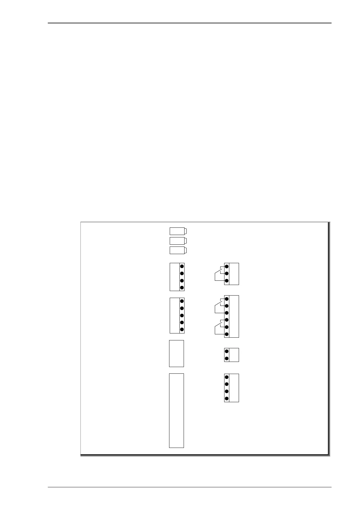
5.3.2 Terminal connection table
Fig. 6
+/-
G
S1
h
GND
rd
br
gr
wh
Level sensor:
G, S1
VS p u m p a n d
Eco Touch-Pro pump
according to the colour
of the cables
AC3
AC2
AC1
N
GND
DC3
GND
DC2
GND
DC1
GND
DC5
GND
DC4
230 V In p ut:
AC1, N = RS
AC2, N = FIL
potential-free
input:
DC1, GND = RS
DC2, GND = FIL
DC4, GND = tem perature
DC5, GND = tem perature
Z1
Z2
Z_ 11
14
12
L
L
N N
Lp
Np
Contact:
Level magnetic valve
11, 14
Contact:
Release Z1, Z2
230 V output to 1~ pump
max. 1.1 kW:
Lp, Np
230 V Su pp l y:
L, N
Contact:
Control z7, z8
z7
z8 z=
(PE distributor terminal present)
WG27.50.124-2-P
Sens3
GND
Sens2

Table of Contents