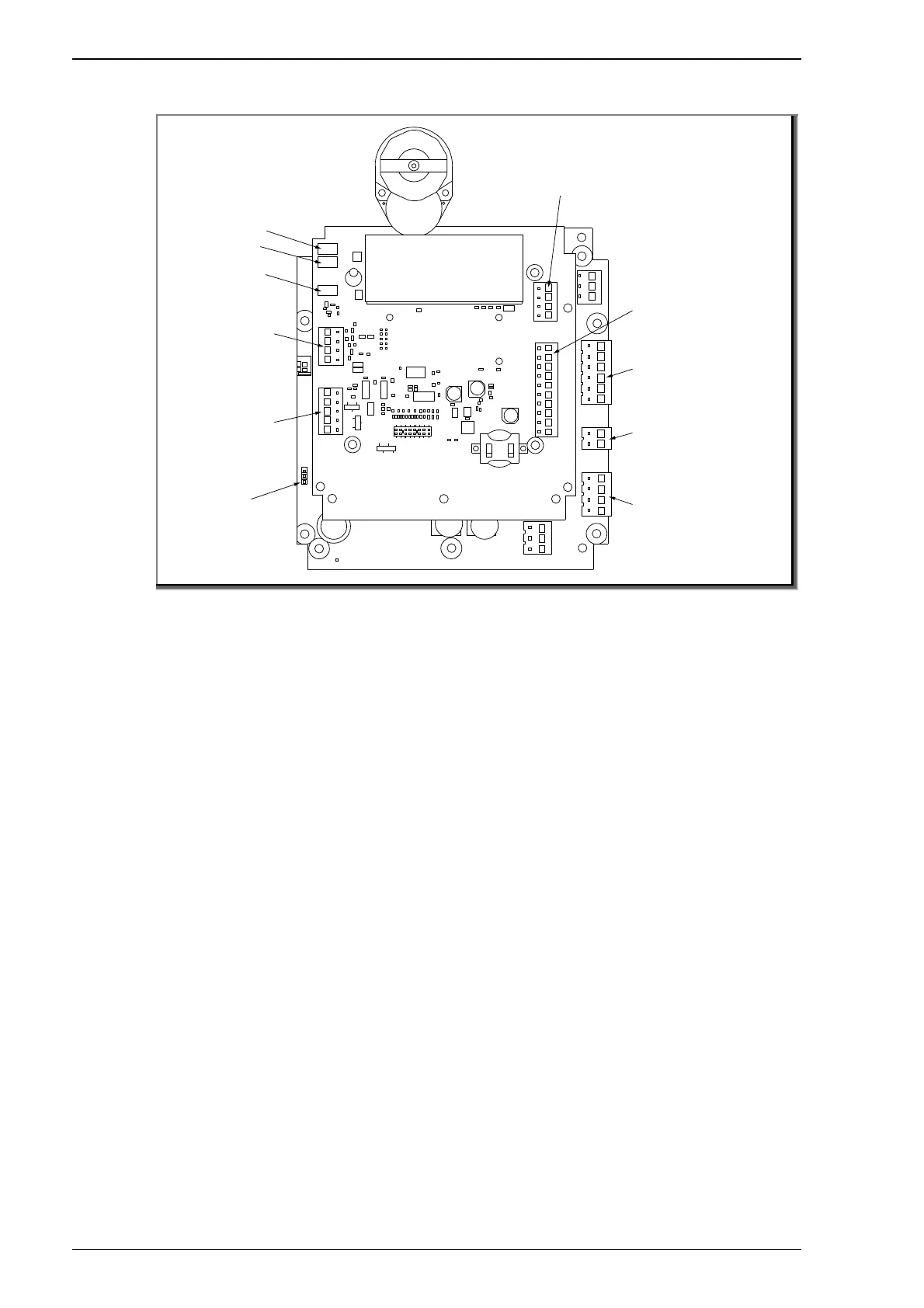
EasyManua.ls Logo

BADU OmniTronic - Connection Diagram

BADU OmniTronic
Print Icon
To Next Page IconTo Next Page
To Previous Page IconTo Previous Page
Loading...
Installation
44 EN 03|2022
5.3.3 Connection diagram
Fig. 7
To connect the cables, first pull the plug off the pin header
upwards. The wires with press-fit wire end ferrules can therefore
be inserted conveniently under the orange opening points without
tools.
The tone signal can be set quieter and louder by replugging the
plugged bridge underneath the connections for the VS-pump. The
plugged bridge can also be removed if necessary. The tone signal
is then no longer available.
3 digital inputs with 230 V
N, AC1, AC2, AC3
3 potential-free digital inputs
DNG, DCx
2 relay outputs
Z1, Z2, Z_, 11, 14, 12
Pump (max. 4 A) with
asynchronous motor
Lp, Np
Supply
L, L, N, N
BADU Eco VS or
BADU Eco Touch
-Pro
control cable
ground, rd, br, gr, wh
Level sensor
(optional)
(PE distributor terminal
present)
315 mAT
4 AT
WG27.50.118-2-P
Sensor 3
GND
Sensor 2
Tone signal volume

Table of Contents