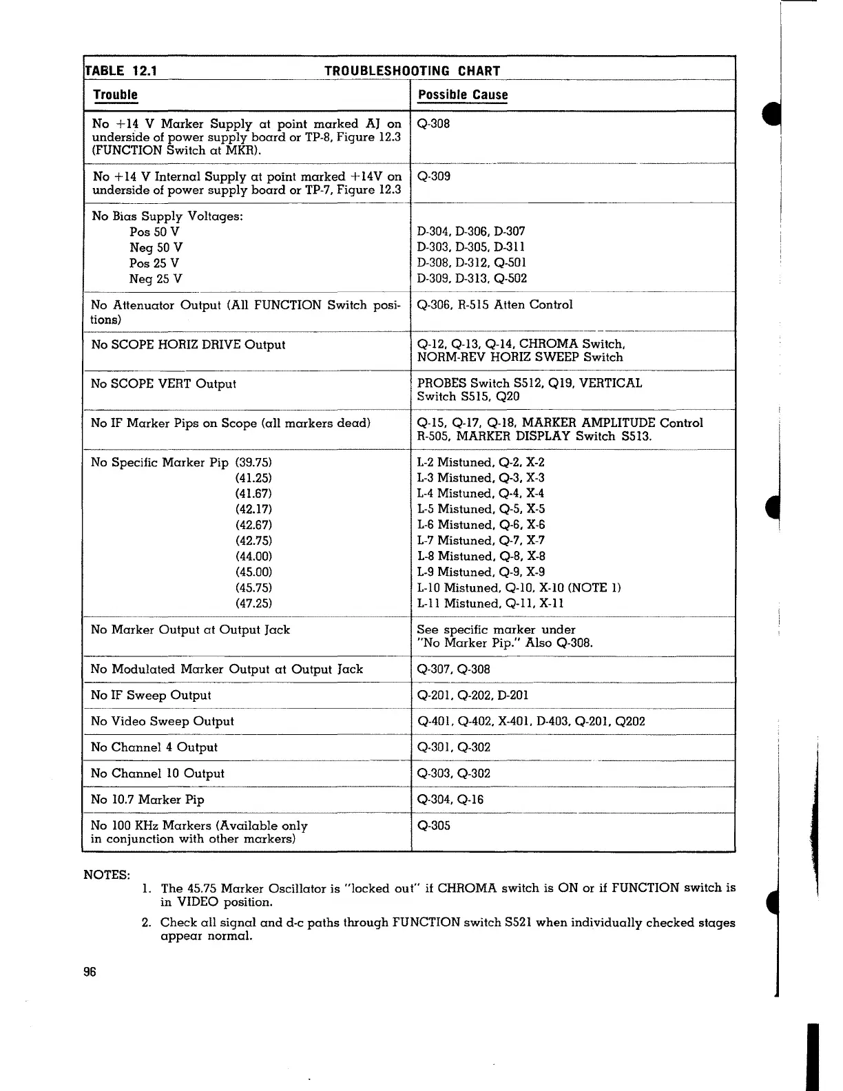
TABLE 12.1
TROUBLESHOOTING CHART
Trouble Possible Cause
No + 14 V Marker Supply at point marked AJ on
Q-308
underside of power supply board or TP-8, Figure 12.3
(FUNCTION Switch at MKR).
------
--------·-
No + 14 V Internal Supply at point marked + 14V on
Q-309
underside of power supply board or TP-7, Figure 12.3
No Bias Supply Voltages:
Pos
SO V
D-304, D-306, D-307
Neg
SO V
D-303, D-305, D-31 l
Pos 25 V
D-308, D-312, Q-501
Neg 25 V
D-309, D-313, Q-502
No Attenuator Output (All FUNCTION Switch posi-
Q-306, R-515 Atten Control
tions)
No SCOPE HORIZ DRIVE Output
Q-12, Q-13, Q-14, CHROMA Switch,
NORM-REV HORIZ SWEEP Switch
No SCOPE VERT Output
PROBES Switch S512, Q19, VERTICAL
Switch S515, Q20
No IF Marker Pips on Scope (all markers dead)
Q-15, Q-17, Q-18, MARKER AMPLITUDE Control
R-505, MARKER DISPLAY Switch S5I3.
No Specific Marker Pip (39.75)
L-2 Mistuned, Q-2, X-2
(41.25) L-3 Mistuned, Q-3, X-3
(41.67) L-4 Mistuned, Q-4. X-4
(42.17)
L-5 Mistuned. Q-5, X-5
(42.67) L-6 Mistuned, Q-6, X-6
(42.75) L-7 Mistuned, Q-7, X-7
(44.00) L-8 Mistuned, Q-8, X-8
(45.00) L-9 Mistuned, Q-9, X-9
(45.75) L-10 Mistuned, Q-10. X-10 (NOTE
I)
(47.25) L-11 Mistuned, Q-11, X-11
No Marker Output at Output Jack
See specific marker under
"No Marker Pip." Also Q-308.
No Modulated Marker Output at Output Jack Q-307. Q-308
No IF Sweep Output
Q-20I. Q-202, D-201
No Video Sweep Output
Q-401, Q-402, X-401. D-403, Q-201. Q202
No Channel 4 Output
Q-30 l, Q-302
- -
No Channel 10 Output
Q-303, Q-302
No 10.7 Marker Pip
Q-304, Q-16
No 100 KHz Markers (Available only Q-305
in conjunction with other markers)
NOTES:
1. The 45.75 Marker Oscillator is "locked out"
if CHROMA switch is ON or if FUNCTION switch is
in VIDEO position.
96
2. Check all signal and d-c paths through FUNCTION switch S521 when individually checked stages
appear normal.
I-
~
I
I
I
I
 Loading...