July 25, 2023
Q5X With Dual Discrete Outputs And IO-Link Instruction Manual
(1)
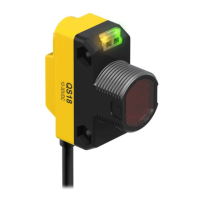
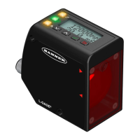
Applying tilt to sensor may improve performance on reflective targets. The direction and magnitude of the tilt depends on the application, but a 15° tilt is often
sufficient.
10
Continued from page 9
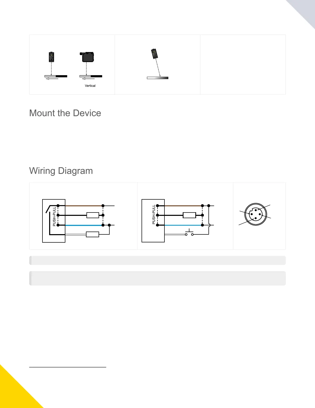
Orientation for a color or luster difference
Horizontal
Orientation
Orientation
(Optimal)
CC
Orientation for highly reflective target
(1)
Reflective
Surface
(optional)
Mount the Device
Wiring Diagram
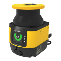
Channel2asPNPDiscreteorPFMOutput
bk (4)
bn (1)
bu (3)
wh (2)
10-30 V DC
CH1
CH2
+
–
Load
Load
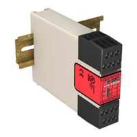
Channel2asRemoteInput
bk (4)
bn (1)
bu (3)
wh (2)
10-30 V DC
CH1
CH2
+
–
Load
Remote Input
NOTE: Openleadwiresmustbeconnectedtoaterminalblock.
NOTE: TheChannel2wirefunctionandpolarityisuserselectable.ThedefaultforthewireisPNPout
put.
Ifabracketisneeded,mountthedeviceontothebracket.
Mount the device (or the device and the bracket) to the machine or equipment at the desired location. Do not tighten
themountingscrewsatthistime.
Checkthedevicealignment.
Tightenthemountingscrewstosecurethedevice(orthedeviceandthebracket)inthealignedposition.
© Banner Engineering Corp.