July 25, 2023
Q5X With Dual Discrete Outputs And IO-Link Instruction Manual
24
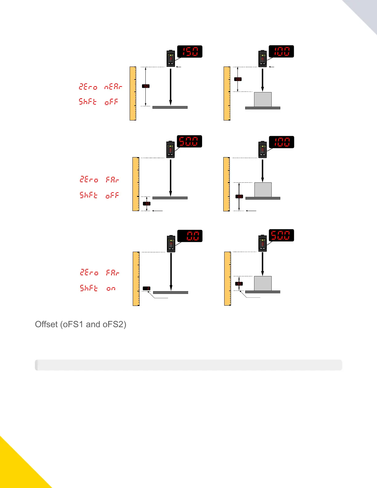
Example Zero and Shift settings
Zero = Near
(Default Setting)
Shift = Off
=
=
Zero = Far
Shift = Off
=
=
Zero = Far
Shift = On
=
=
Display Reference Display Reference
50 cm
Display Reference Display Reference
Display Reference
Display Reference
cm
200
0
100
50
150
cm
200
0
100
50
150
cm
200
0
100
50
150
cm
200
0
100
50
150
cm
-50
150
50
100
0
cm
-50
150
50
100
0
50 cm
50 cm
Offset (oFS1 and oFS2)
UsethismenutosetanoffsetfromthetaughtsurfaceduringaTEACHprocedure.
Thismenuisavailableonlyifonepointwindow(foregroundsuppression)modeoronepointbackgroundsuppressionmode
isselected.ForChannel2,theoutputmustbesettolightoperateordarkoperate.
NOTE: Thenumberthatfollowsonthedisplayindicateswhichchannelisselected.
Theoffsetisautomaticallycalculatedormanuallydefinedasaconsistentlyappliedvalue.Autoisthedefaultoption.Use+/
toselectavalue.Valuesincreaseordecreasebyupto191cmfor2000mmmodelsandupto497cmfor5000mmmodels.
ForBGSmode,thedefaultisAutobecausetheQ5Xautomaticallyselectswheretopositiontheswitchpoint.ForFGSmode,
thedefaultis0becausethewindowiscenteredaroundthetaughttarget.
ApositiveoffsetvaluealwaysshiftstheswitchpointlocationortheFGSwindowtowardsthesensor.
The taught surface must be inside of the defined sensing range. When the teach mode is set to FGS, some portion of the
window must be located within the sensing range. When the teach mode is set to BGS, the offset value must be within the
defined sensing range. If an offset value falls outside of the sensing range, a message displays. See the applicable TEACH
procedureformoreinformation.
© Banner Engineering Corp.