7. Input & Communication
7.4 Cinema C ontroller
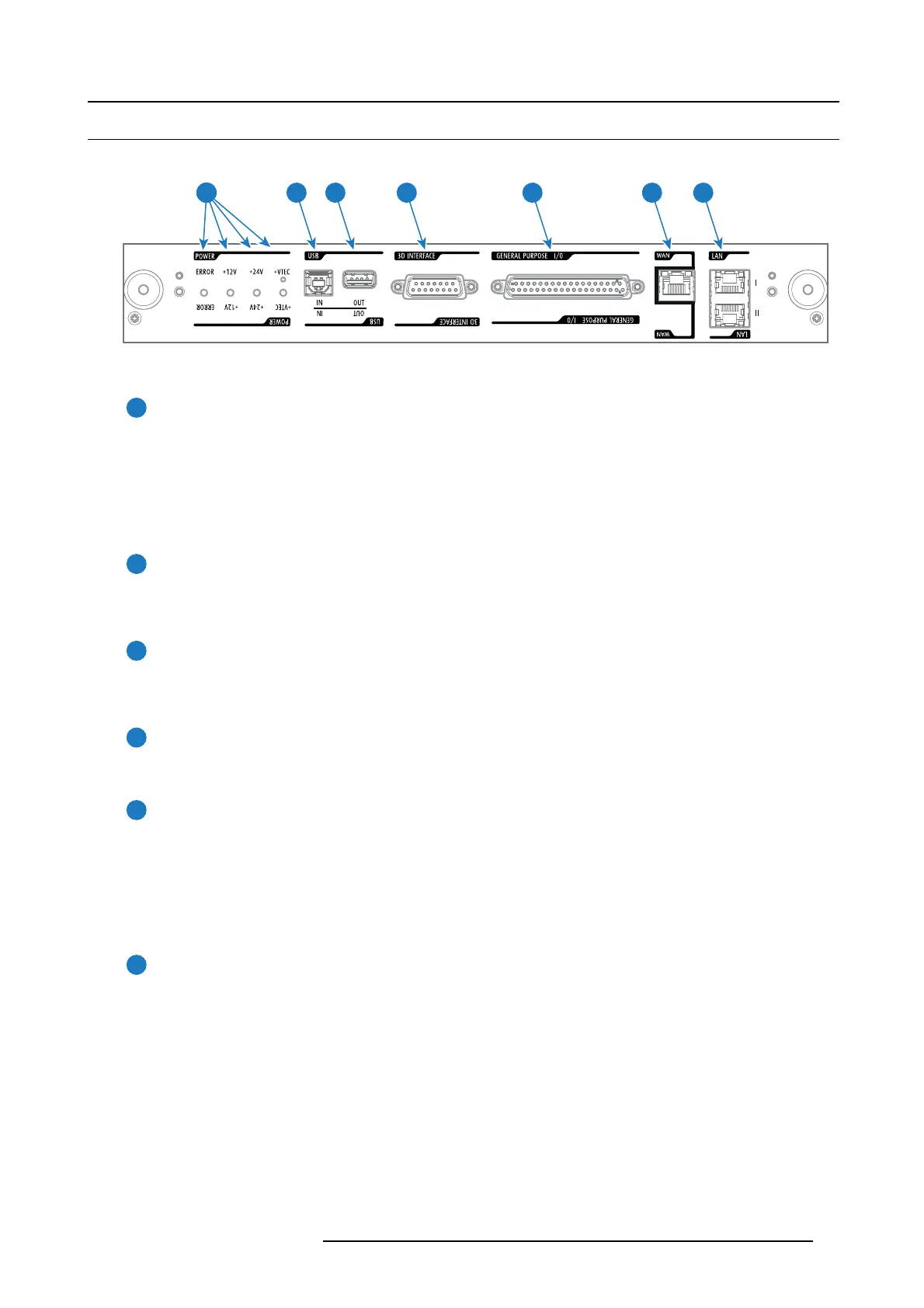
Location of the communication ports
5 6 74321
Image 7-4
Functionality
1
Diagnostic LEDs
The front plate of the Cinema Controller con tains 4 diagnostic LEDs to display the status o
f the power supply (reference 6
image 7-4):
• +VTEC supply (not used on DP 2K-E series projector).
• +24V supply.
• +12V supply.
• gener al power supply (ERROR).
2
USB IN port
The Cinema Controller is equipped with a USB port, type “B” connector, (reference 5 image 7-4) to connect upstream devices
(E.g. P C). This USB po rt is used to communicate with the projector via R S232 comm ands (Virtual comport). T he USB
IN port rem ains oper ational in S leep mode.
3
USB OUT port
The Cinema Controller is equipped with a U SB port, type “A” connector, (reference 4 im age 7-4) which can be us ed to power
handheld devices within USB s pec (M AX 500mA/5V]. No other functionality s upported (Future expansion). T he U SB
OUT port remains operational in Sleep mode.
4
3D INTERFACE
3D interface port (reference 3 im age 7-4). Can be used to connect external 3D devices to the projector. All signals necessary
for 3D projection ca n be provided via this connector. The 3 D interface port is disabled if the projector is in Sleep mode.
5
GENERAL PURPOSE INPUT/OUTPUT (GPIO)
This 37 pin connector (reference 2 image 7-4) can be used to send or receive trigger signals from other devices. These
input/output p ins can b e programmed by macros created with the Com munica tor software. See user’s guide of the
Communicator, s ection Macro editor, for more information about this functionality. Note that the G ene ral Purpose Inputs
accept 24 volt maximum. The GP IO rem ains operational when the projector is in S leep mode. So, if the factory predefined
macro to wak e up the projector is assigned to one of the free GPI input pins the projector can be awakened v ia GP IO.
Enter or leave S leep mode can also be done with G PIO via two p redefined M acros (not editable).
6
Wide Area Network (WAN)
Wide Area N etwork (WAN: 10/100/1000 base-T). U se this Ethernet port (reference 6 image 7-4) t o connect the network
which contains the DHCP server.
Once connected to the WAN, us ers c an access the projec tor from any location, inside or outside (if allowed) their company
network using the Communicator software. This software locates the projector on the network if there is a DHCP se rver or
the user can insert the correct IP-address to access the projector. Once accessed, it is possible to check and manipulate a ll
the projector settings. Remote diagnostics, control and mon itoring of the projector can then bec ome a daily and very sim ple
operation. The network c onnectivity allows detection of potential errors and consequently improves service time.
R5906693 DP2K-E SERIES 19/06/2015
45