R5913197 /02 SP2K-S44
4.3 Connecting the projector with the power net
WARNING: The total electrical installation should be protected by an appropriate rated and readily
accessible disconnect switch, circuit breakers and ground fault current interrupters. The installation
shall be done according to the local electrical installation codes.
CAUTION: ALL POWER CONNECTIONS to the SP2K-S projector are made to the tree-terminal
strip located on the mains board behind the operator side cover and mains cover of the projector.
CAUTION: The cross-sectional area of the conductors in the Power Supply Cord shall be not less
than 2.5 mm
2
or AWG 12.
Required tools
• Flat screwdriver
• Open-end wrench 24 mm
• Torx screwdriver T20
Required parts
Certified AC power supply cord 2.5 mm², 12 AWG, min. 300 V.
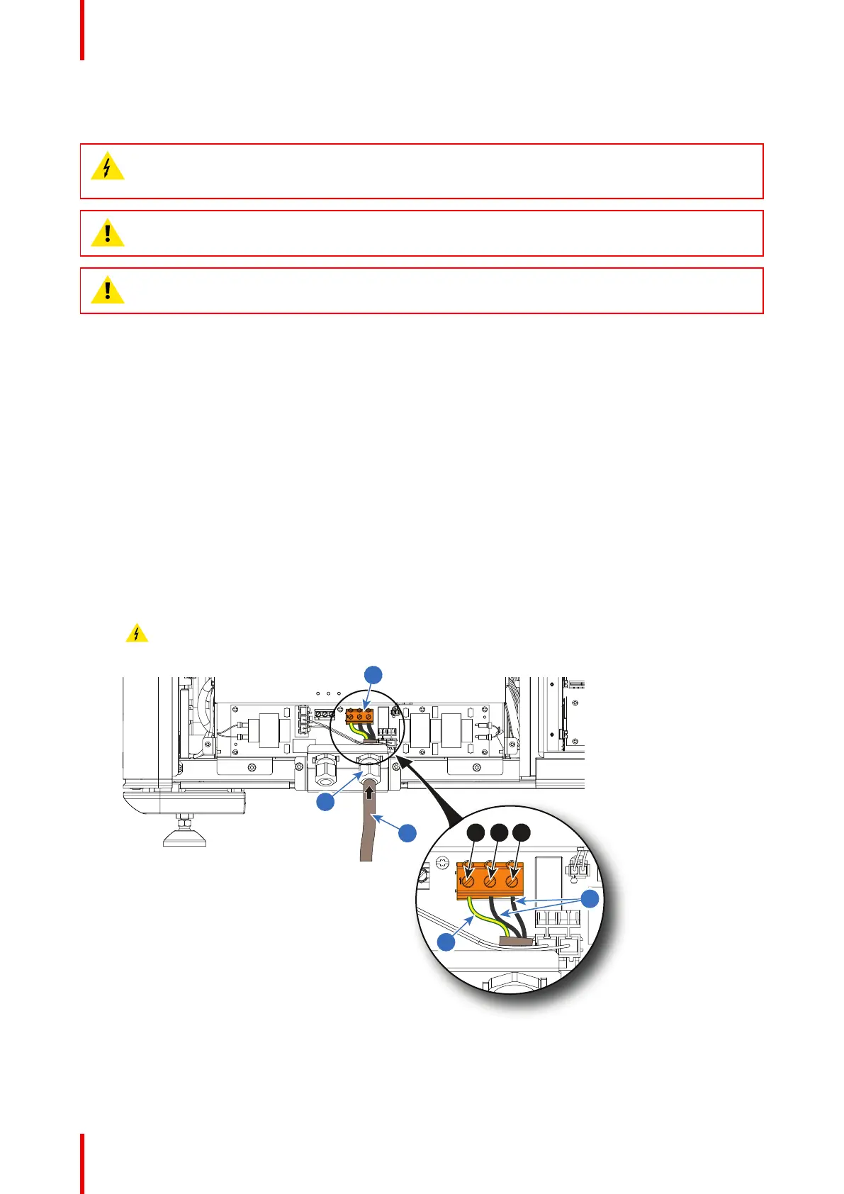
How to connect the main AC power with the projector
1. Make sure the net input cover has been removed. For more info, see “Accessing the power connections”,
page 43.
2. Guide the AC power cord (reference 1) through the cable gland (reference 2).
3. Connect the wires (references 4 and 5) to the 3–terminal strip (reference 3) as illustrated. Use a torque
screwdriver to fasten the screws of the 3-terminal strip with a torque of 1.2 Nm.
Warning: Always connect the PE wire (reference 4) first, then the other wires.
Image 4–6
1 AC Power cord
2 Cable gland
3 3–terminal strip
4 PE wire
5 Phase and neutral wires
PE Protected Earth connector
N Neutral connector
L Phase connector
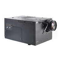
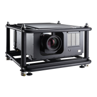
Physical installation projector