59
925.916.2 - GBINSTRUCTIONS PERTAINING TO THE INSTALLER
IMPORTANT: in the case of conversion from natural gas to propane (LPG), the following operations must be performed
before calibrating the gas valve as illustrated above:
• Turn adjuster screw (V) on the gas valve through the number of complete revolutions specied in table 3 or 3.1;
• On the control panel display set ignition power parameters H608 and H611. The values to be input are given in table 3
or 3.1. The programming methods are described in chapter 17;
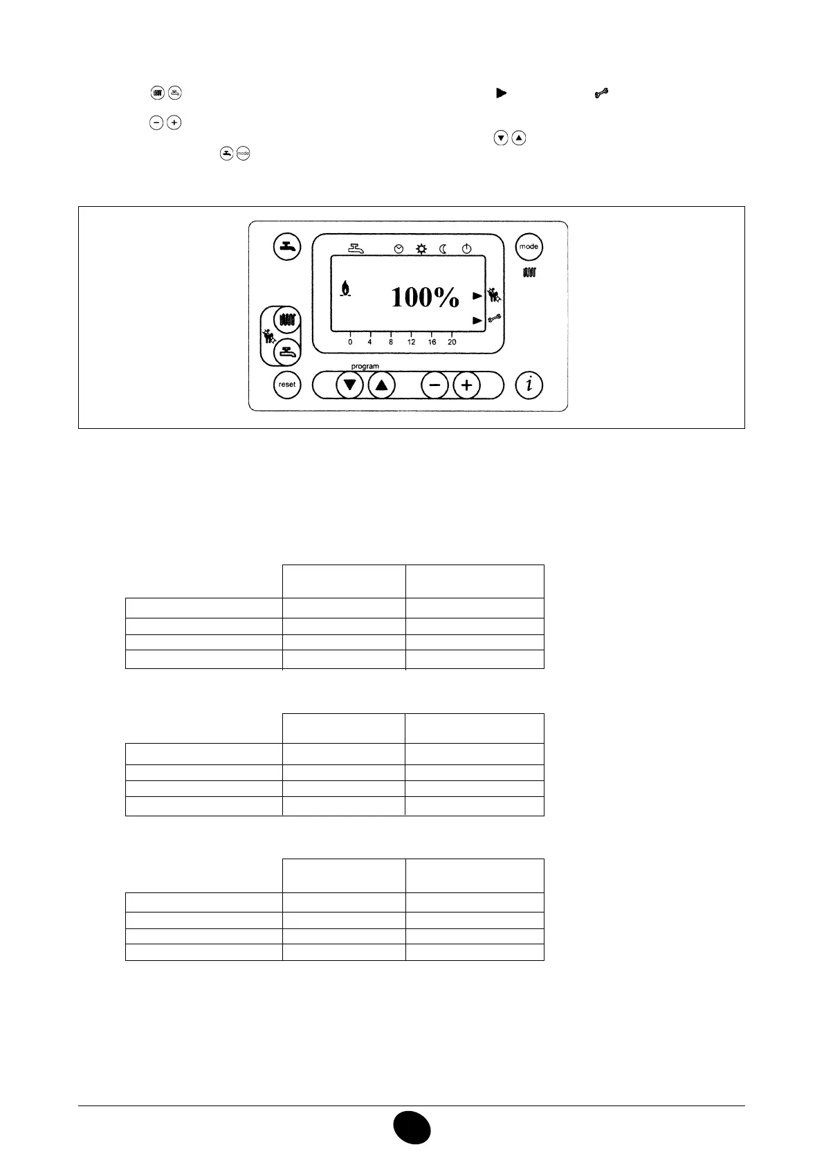
To simplify calibration of the gas valve, the “calibration function” can be set directly on the boiler control panel by pro-
ceeding as follows:
1) Press the keys (2-3) together until the display shows the pointer “ ” alongside the symbol (about 6 secon-
ds).
2) Press the
keys to set the fan speed at the minimum and maximum heat output (%PWM);
N.b - to set the
minimum and maximum heat output quickly, press the keys respectively;
3) press either of the two keys to exit the function..
0307_2201
Figure 15
LUNA3 SYSTEM HT 1.240 MP
G20 - 2H - 20 mbar G31 - 3P - 37 mbar
CO
2
max. heat output 8,7% 10%
CO
2
min. heat output 8,4% 9,5%
CO max
< 250 ppm < 250 ppm
Gas nozzle 7,5 mm 7,5 mm
LUNA3 SYSTEM HT 1.180 MP
G20 - 2H - 20 mbar G31 - 3P - 37 mbar
CO
2
max. heat output 8,7% 10%
CO
2
min. heat output 8,4% 9,5%
CO max
< 250 ppm < 250 ppm
Gas nozzle 5,7 mm 5,7 mm
Table 1c
Table 1b
LUNA3 SYSTEM HT 1.330 MP
G20 - 2H - 20 mbar G31 - 3P - 37 mbar
CO
2
max. heat output 8,7% 10%
CO
2
min. heat output 8,4% 9,8%
CO max
< 250 ppm < 250 ppm
Gas nozzle 12,0 mm 12,0 mm
Table 1a
 Loading...