Installation Requirements
38 BD406/PBD406 DV16401.03 Issue 04 May 2021
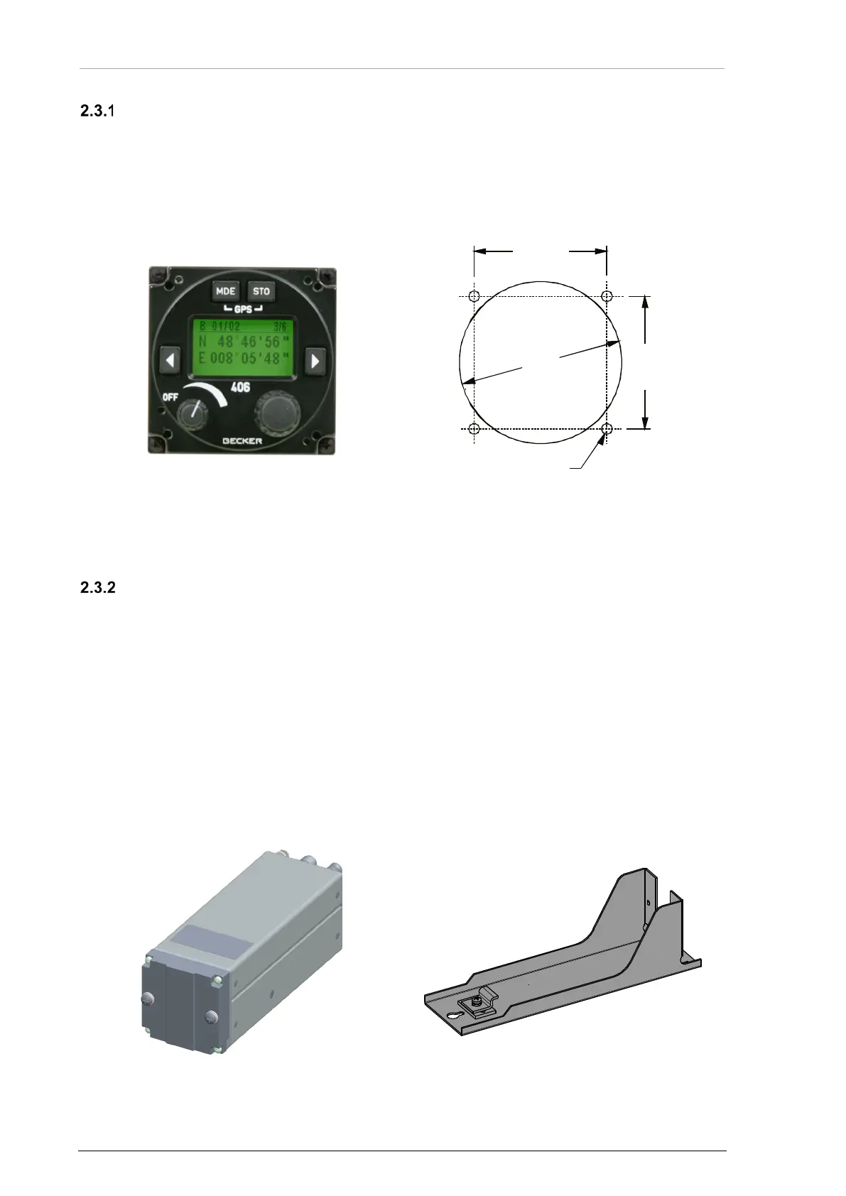
Rear Panel Installation - BD406 with Control Head
• The BD406 with control head is made for rear panel installation.
• The four screws for installation are included with the delivery.
• Keep a minimum of 5 mm between the BD406 and other avionics for air circulation.
• More information please see: Dimensions, "BD406 with Control Head" page 40.
Dimensions mm (inch)
Figure 8: BD406-(XX1) (front view)
Figure 9: Drilling Template -Rear-Panel Installation
Avionic Bay Installation - BD406 without Control Head
• The BD406 without control head and mounting kit MK4401 are for avionic bay installation.
• Keep a minimum of 5 mm between the device and other avionics for air circulation.
Order of Installation
• Install MK4401 mounting frame in avionic bay environment, using three countersunk
screws.
• Remove the two screws from device front plate. Loosen the securing-plate on mounting
frame.
• Slide the device into the mounting.
• Push the security-plate into the locking slot and tighten the securing-plate. Tighten the
device with the two screws from device front plate.
• Dimensions see, "BD406 without Control Head" page 41, "BD406 without Control Head
with Mounting Kit MK4401" page 42.
Figure 10: BD406 without Control Head (front view)
58
(2.283 in)
47.3
±0.2
(1.862
±0.008
)
47.3
±0.2
(1.862
±0.008
)
Ø 3.5
(Ø 0.138)