Installation and Operation
Electrical Interface
DV16401.03 Issue 04 May 2021 BD406/PBD406 51
Connector Pin Assignments - PBD406
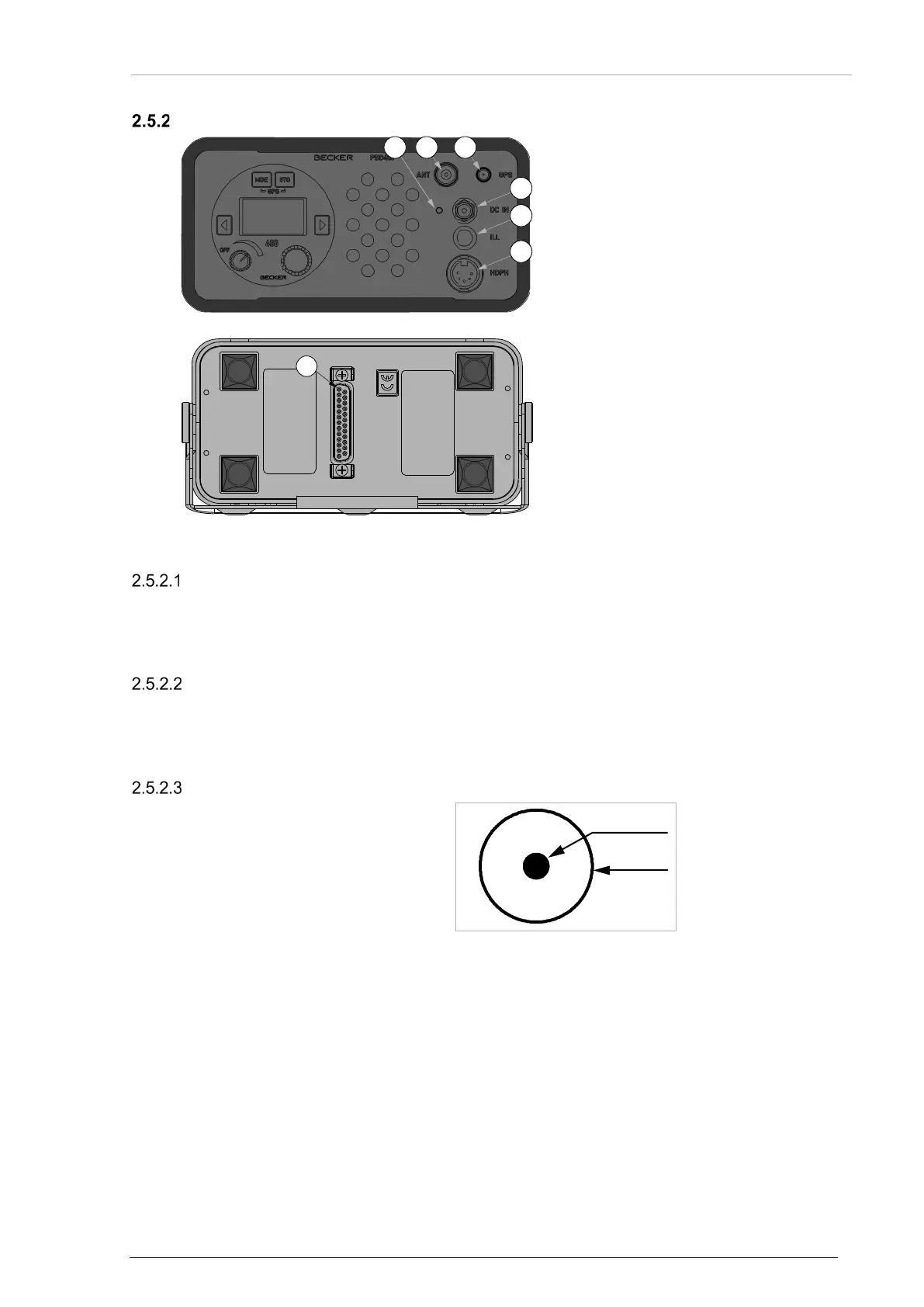
Figure 21: PBD406 – Connector Layout (front side)
J4: 406 MHz antenna connector
J5: GPS antenna connector
P3: External DC voltage
P2: Headphone / speaker output
B1: Illumination button
L2: LED, external voltage indicator
--: Speaker
Figure 22: PBD406 – Connector Layout (rear side)
406 MHz Antenna Connector (ANT)
Position J4:
Type: BNC type
GPS Antenna Connector (GPS)
Position J5:
Type: GPS SMA Jack
External DC Voltage (DC IN)
Type: DIN Jack
Figure 23: PBD406 – Connector P3 (front side)
• Connector P3 for external power supply.