84 BD406/PBD406 DV16401.03 Issue 04 May 2021
User Interface - PBD406
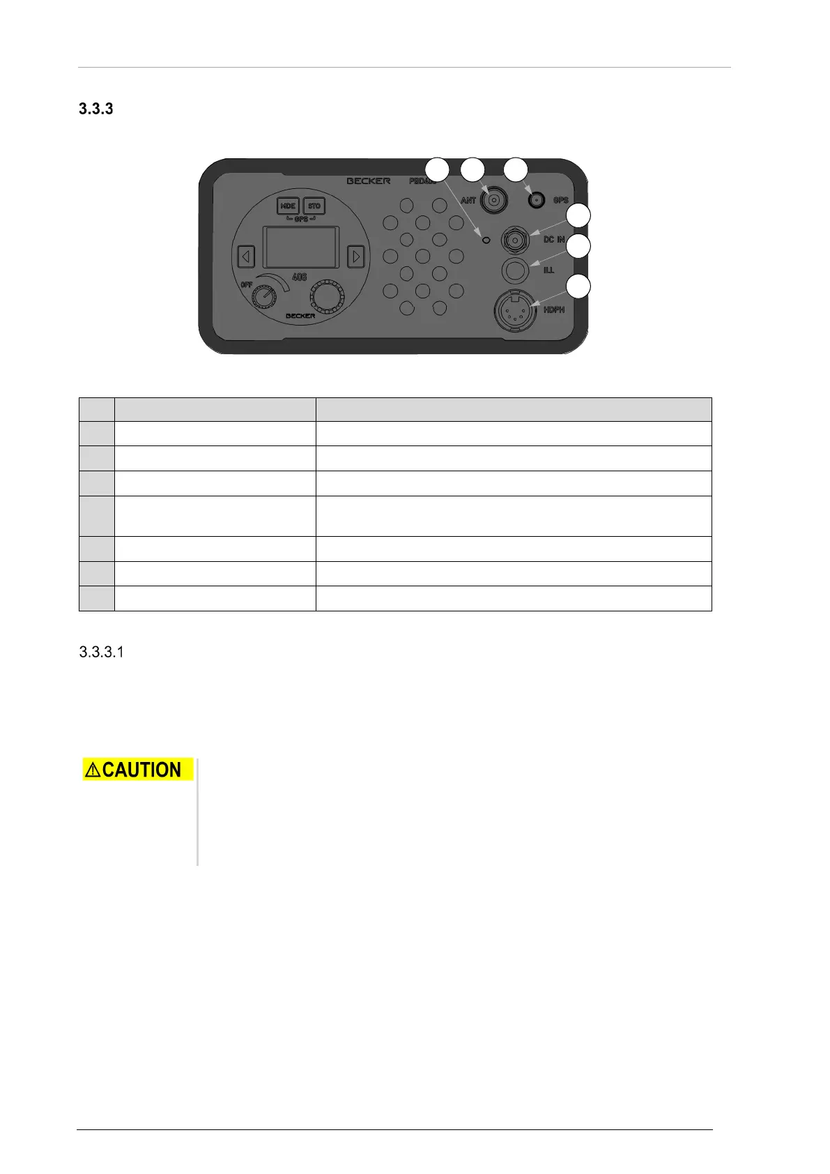
BD406 is part of the portable version PBD406. PBD406 has the same set of controls as BD406 control
head plus elements on the front panel of the housing.
Figure 37: User Interface - PBD406
406 MHz antenna connector
Connector P3 for external power supply.
P2
Headphone / speaker output
Connector P2 is internally connected to the related pins of
BD406 P1 connector.
Push to set on screen backlight for approx. 15 s.
External voltage indicator.
Recommendations:
The portable UHF 406 MHz antenna has a fixture to attach the antenna to any object that extends
PBD406 reception range during a rescue mission (a mast, etc.). The antenna can be also held in hand
(near BNC connector) however this can decrease the effective range of a signal reception.
PBD406 has a dedicated GPS antenna. It must be connected directly to the SMA socket J5.
• Connect active GPS antenna to the BD406/PBD406 only when the device is
not powered-on.
• Do not connect or disconnect the GPS antenna when the BD406/PBD406
operates, as the internal GPS receiver calibrates the noise floor on power-up.
• To connect the antenna after power-up can cause an extended acquisition
• The GPS antenna must have direct view to sky to maximize its effectiveness.
• It must not be covered by any objects, as it degrades quality and reliability of the fixed
position.
• Any obstruction near the GPS antenna can cause significant reduction of the precision.
Interference obstacles are e.g.: buildings, trees, fences, cables etc.
o Obstructions can have an effect that the receiver receives a decreased number of
satellites and that the strength of satellite geometry is decreased (high PDOP values).