Aircraft Wiring
58 BD406/PBD406 DV16401.03 Issue 04 May 2021
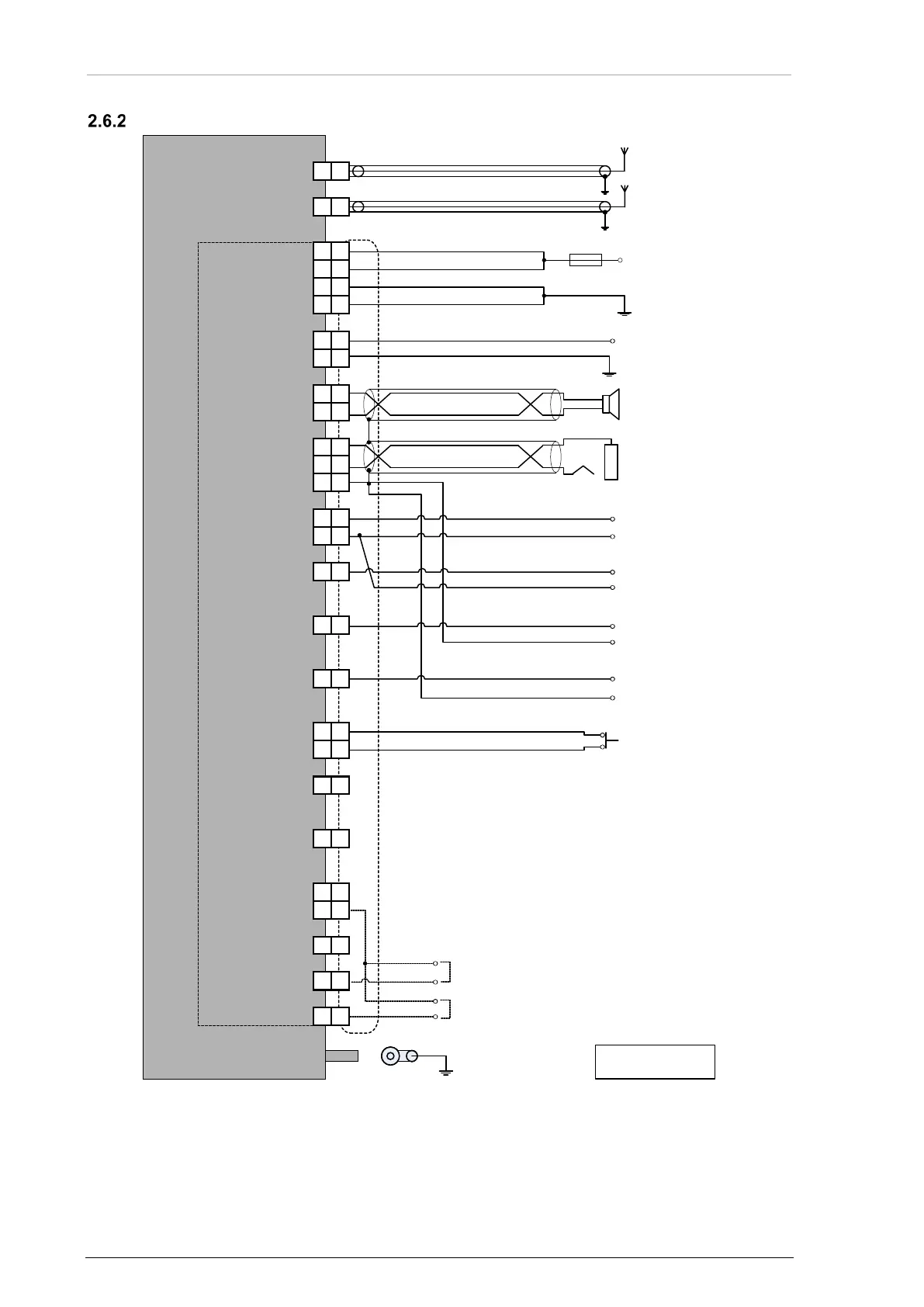
Wiring - BD406 with Control Head, P1 Connector and Antennas
Figure 25: Wiring - BD406 with Control Head, P1 Connector and Antennas
Grounding bolt
Coaxial cable RG223/U or RG58C/U
GPS Antenna
RF Antenna
Coaxial cable RG223/U or RG58C/U
9...32 VDC supply
Fuse 2.5 A
2x A
WG20
AWG20...22
Open collector
Open collector
Open collector
Open collector
2x A
WG20
Power supply GND
AWG16 wire,
as short as possible
All cables: AWG22
if not specified
2424
1313
1212
2525
99
88
1515
1414
22
11
2
1
1616
1717
44
55
77
66
2222
2020
1919
1010
2121
33
1818
1111
2323
44
55
77
66
2222
2020
1919
1010
2121
1818
1111
2323
2424
1313
1212
2525
99
88
1515
1414
22
11
2
1
1616
1717
33
PWR_SUPP
PWR_SUPP
PWR_GND
PWR_GND
ILLUM+
ILLUM-
SPKR+
SPKR-
HDPH+
ANT BNC connector
GPS ANT TNC connector
DO_GND
/MSG
/PWR_EVAL
/GPO_0
HDPH-
/GPI_1
DI_GND
/GPI_0
/SDI_9
/SDI_10
DI_GND
/GPI_2
DO_GND
/GPO_1
/ON
/GPI_CH
P1
BD406 with control head
I
load max.
20 mA
/MSG out
Dimming 14V/28V
Headphone 150 Ω
/PWR_EVAL out
Speaker 4 Ω
I
load max.
20 mA
Homing
/GPO_0 out
I
load max.
20 mA
/GPO_1 out
I
load max.
20 mA
ARINC 429 bit 9 configuration
(configurable only during installation)
ARINC 429 bit 10 configuration
(configurable only during installation)