Electrical Interface
48 BD406/PBD406 DV16401.03 Issue 04 May 2021
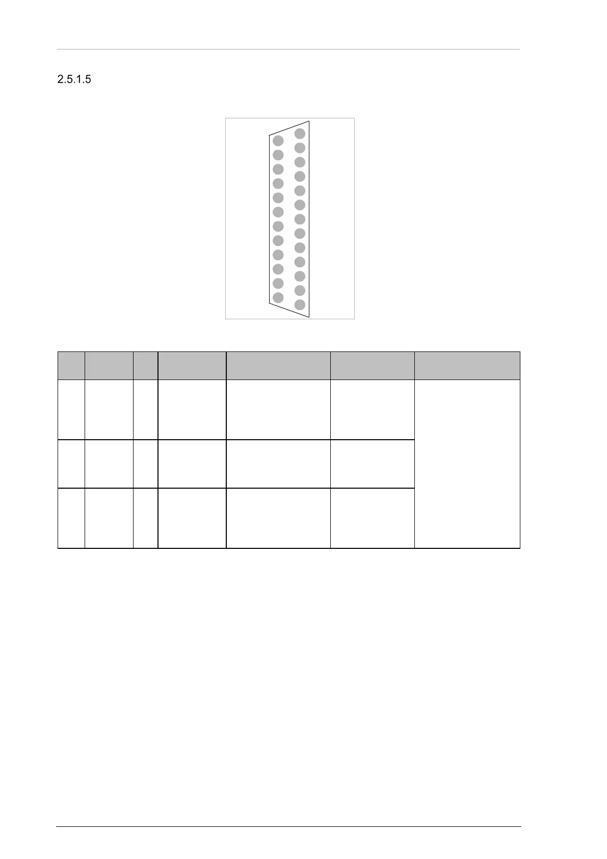
Device Connector J1 - Serial Interfaces
Position 4:
Type: DB-25 D-SUB, 25-pol. female connector, slide-in fastener.
Figure 20: Connector Layout J1 - Serial Interfaces (rear side)
J1
Type I/O Name Function Recommended
Remarks
negative bus of the
transmitter.
Not used for BD406
compliant output
interface.
of the transmitter.
Not used for BD406
positive bus of the
transmitter.
Not used for BD406
12
13
11
10
9
8
7
6
5
4
3
2
1
14
15
16
17
18
19
20
21
22
23
24
25
IF2TX
IF0TX_GND
IF0TX+
IF0TX-
IF1RX-
IF1RX_GND
IF1RX+
IF1TX-
IF1TX_GND
IF1TX+
IF2RX_GND
IF2RX
IF2TX_GND
IF4TX+
IF3TX
IF3RX_GND
IF3RX
IF3TX_GND
IF4RX-
IF4RX_GND
IF4TX-
IF4RX+
IF4TX_GND
DI_GND
/SRV_EN
J1