Installation and Operation
Electrical Interface
DV16401.03 Issue 04 May 2021 BD406/PBD406 45
2.5 Electrical Interface
Connector Pin Assignments - BD406
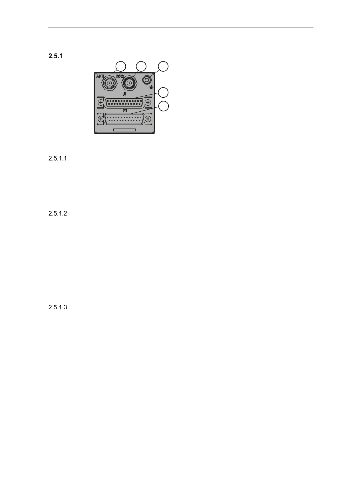
Figure 18: BD406 – Connector Layout (rear side)
1: 406 MHz antenna connector
2: GPS antenna connector
3: Grounding bolt
4: J1 (serial interfaces)
5: P1 (digital & analog I/Os)
406 MHz Antenna Connector (ANT)
Position 1:
Type: BNC type
Nominal impedance: 50 Ω
Recommended cable type: RG223/U (RG58C/U acceptable).
GPS Antenna Connector (GPS)
Position 2:
Type: TNC type
Recommended cable type: RG223/U (RG58C/U acceptable).
The antenna input delivers bias voltage in a range of 2.75...3.40 VDC, maximal load current 50 mA to
supply active antennas.
The device operates with active antennas:
• Antenna minimum gain: 15 dB
• Antenna maximum gain: 50 dB
• Antenna maximum noise: 1.5 dB
Grounding Bolt
Position 3:
Type: M4 thread screw, washers and nuts included.
Use this bolt for low impedance grounding of the device.
Note: Low impedance grounding is essential to prevent damage or malfunction in case of
indirect lightning, EMI and HIRF conditions.