Safety Manual / Explosion Protection Manual 6 Safety Instructions
56926BA26, Rev. 06, 04/2019
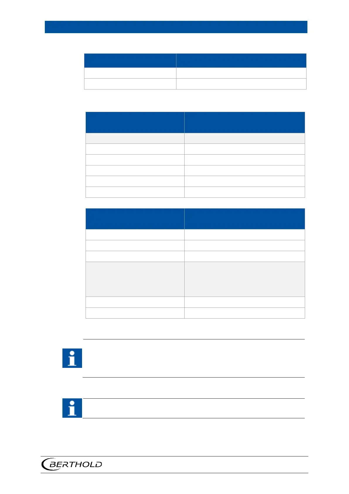
Electric parameters for the supply
Supply and signal circuit (FSK)
max
Electrical safety parameters for the associated equipment
Supply and signal circuit (FSK)
Rectangular characteristic curve
i
i
max. internal inductance L
i
max. internal capacitance C
i
Signal output (terminal 3, 4)
Thermometer circuit (PT100) linear char-
acteristic curve
o
o
Maximum concurrently
permissible external values of
jointly acting reactance
(C
i
, L
i
already considered)
IIC
o
The above ranges for ambient temperature (T
a
) only apply to free-standing
mounted detectors. If the detector is not free-standing, this can lead to an ad-
ditional increase in surface temperature (e.g. by reflection of heat). In this case,
the ambient temperature (T
a
) must be accordingly reduced in order to make
sure that the maximum surface temperature is not exceeded.
See chapter 7 for the “Control Drawing” and details on the explosion protec-
tion concept.