56926BA2, Rev. 02, 04/2019
4.5 Installation on a Vessel
For mounting the detector on the vessel, the mounting clamps must first be
mounted on the detector (see chap. 4.3). Examples are shown in Fig. 8, Fig. 9 and
Fig. 10. Appropriate mounting fixtures (e.g. mounting brackets, platforms, etc.) are
to be provided by the operator. The dimensions of the detector and the mounting
clamps (see Appendix) should be observed. The orientation of the system compo-
nents (radiator/shielding and detector) to each other and to the measuring range
is described in detail in the operating manual of the corresponding transmitter.
The cable bushing and cable inlet should be positioned so that no water can flow
along on the cable into the bushing.
The distance from the middle of the detector to the vessel surface or surface of
heat insulation should be approx. 100 mm.
Care should be taken during mounting to avoid as far as possible heat transfer
from the vessel via the clamps to the detector.
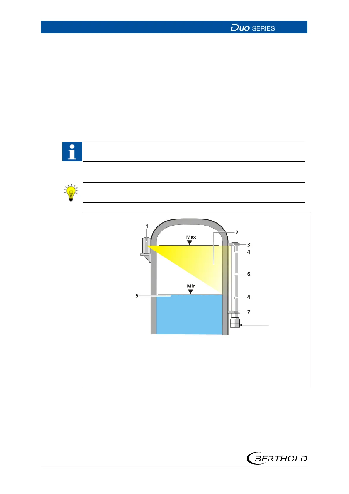
2
3
4
5
6
7
Point source with shielding
Radiation beam
Upper mounting clamp
Marking groove on the detector
Level
Rod detector
Lower mounting clamp
8 Fastening of Rod Detector