PT100 circuit
U
O
= 16.8 V
I
O
= 33 mA
P
O
= 139 mW
L
O
= 15 mH
C
O
= 190 nF
Measurement circuit
U
i
= 17,64 V
I
i
= 81 mA
P
i
= 1.4 W
L
i
= 2.7 µH
C
i
= 2.42 nF
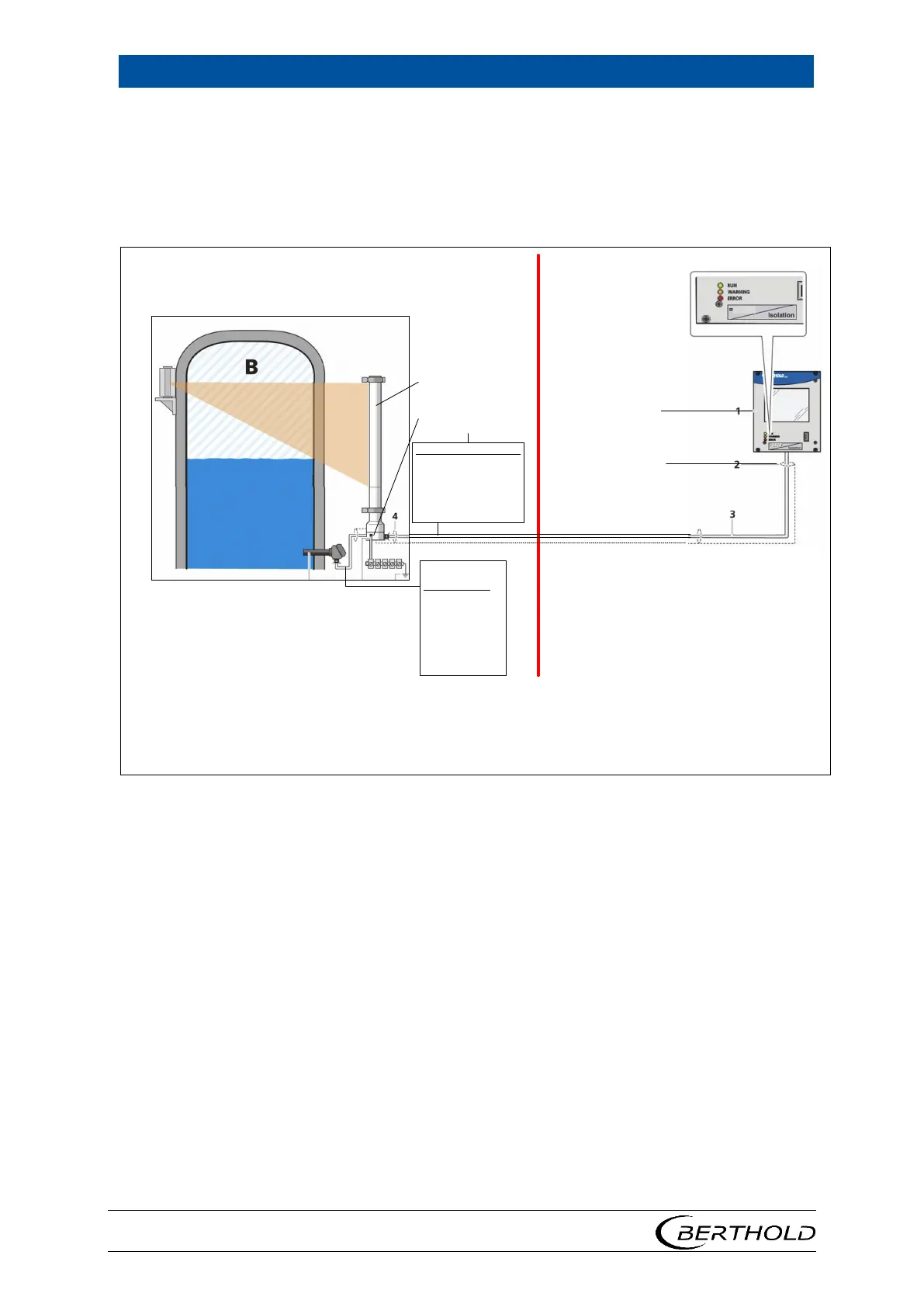
Hazardous Location
(Class I) Zone 1 / Zone 21
Class I Division 1, Groups B,C,D (A: US only)
Class II Division 1, Groups E,F,G, Class III
Non Hazardous Location
LB 4700-..-I. detectors:
Associated Apparatus
with safe galvanic isolation
Isolation between
screen and housing ≥ 500 V
• Install acc. valid local rules (directive 2014/34/EU, NEC or CEC, national authorities).
• Warning; Repair only by persons authorized by Berthold Technologies.
• Connection cable must be suitable for a continous operating temperatue ≥ T
a
+ 15 K
• Entity Installations must satisfy: U
O
≤ U
i
, I
O
≤ I
i
, P
O
≤ P
i
, L
O
≥ ΣL
i
+ L
C
, C
O
≥ ΣC
i
+ C
C
• Mains Supply must not generate over 250 V
AC
.
• Short circuit current of mains supply
must not exeed 1.5 kA.
• For non intrinsically safe installation
„Denergize and wait 2 minutes before opening.“
• LB 4700-..-F. detectors:
A seal shall be installed within 18 inch of enclosure
Maintain the type 4X degree of protection of the
enclosure. Use only listed conduits or cable glands.
• LB 4700-..-1 or LB 4700-..-I. detectors:
To maintain ingress protection install with IP66 / IP68.
LB 47x System – 2019-01-08 – Control Drawing, Rev. 00
3,0 kV
3,0 kV
Electronic compartment
Ex d / XP
Terminal compartment
Ex e / Ex ib / XP
LB 4700