82
Logic Gates
Most Logic Gates have no Control Dialog Boxes. They are used only to customize behavior of other control
functions in the system. Logic Gates are connected between the output and input control nodes of other
components in the layout. These components can represent internal or external control functions.
Examples
Internal
: Auto Mixer output nodes; Ducker input/output nodes; Remote Preset Button input nodes.
External
: Select 8 output nodes; Volume/Select 8 output nodes; Logic Box input/output nodes.
Logic Gates alter the normal operation of component control outputs in the following ways:
NOT
: produces opposite/inverted operation (input ON turns output OFF; input OFF turns output ON).
AND
: all inputs ON causes output to go ON (any inputs OFF causes output to go OFF).
NAND
: all inputs ON causes output to go OFF (any inputs OFF causes output to go ON).
OR
: any inputs ON causes output to go ON (all inputs OFF causes output to go OFF).
NOR
: any inputs ON causes output to go OFF (all inputs OFF causes output to go ON).
XOR
: any inputs (except all) ON causes output to go ON (all inputs OFF/ON causes output to go OFF).
Flip Flop
: produces toggle/latching operation (input ON changes output state, ON/OFF).
Logic State
: provides manual latching operation only (includes no input node).
NOTES: NOT and Flip Flop gates have only a single input per output, whereas most other gates have
multiple inputs, up to 8. Flip Flop gates provide a control dialog box, for establishing their initial output
state. Also, unlike most other blocks, multiple control output nodes may be connected to a single control
input node on a Flip Flop gate. Control Dialog boxes for Logic State gates can be minimized to create user
control surfaces (see Customizing Component Objects).
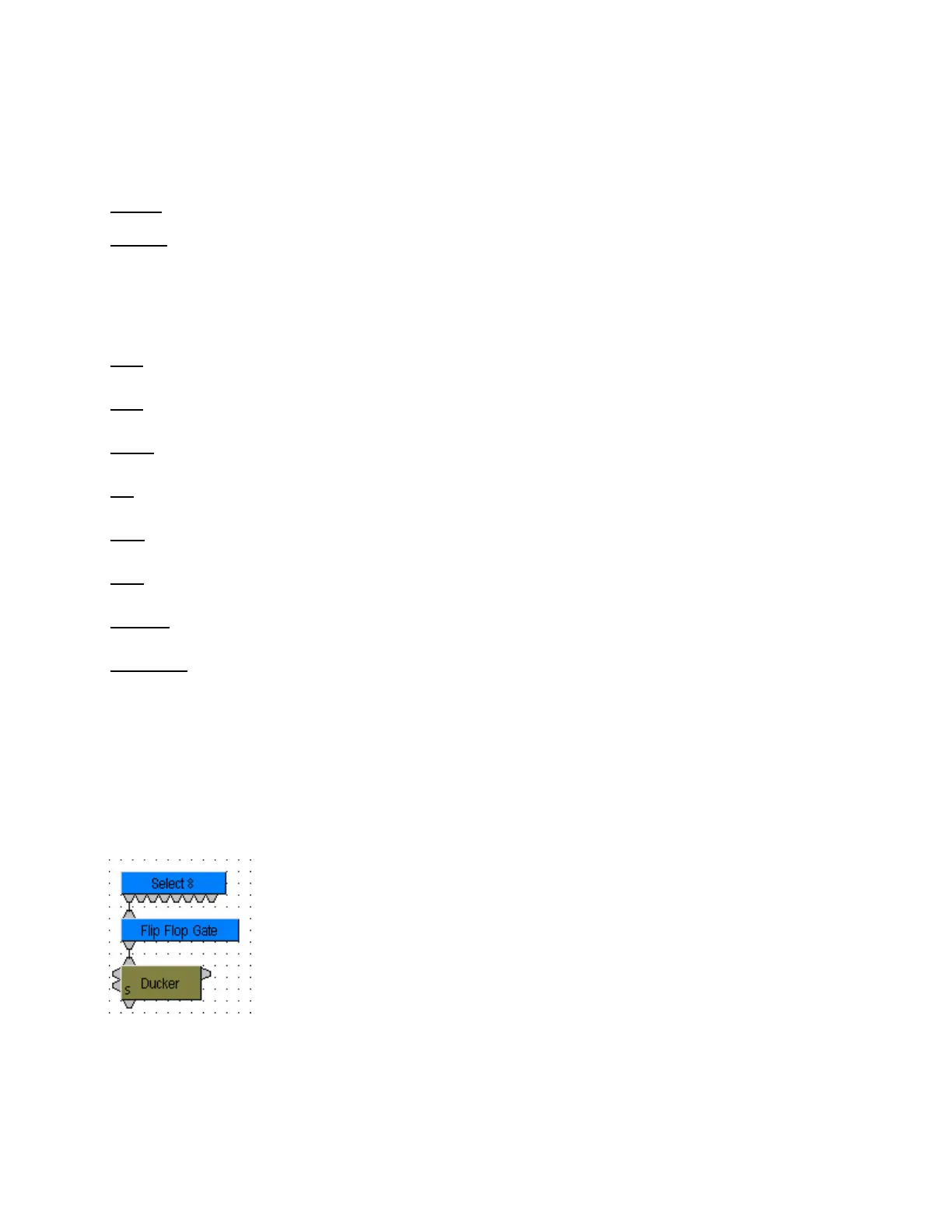
Sample Application
Normally, a Select 8 control output connected to a Ducker control
input provides a momentary operation (ducking occurs only as long as
the Select 8 control is being pressed). However, connecting a Flip
Flop Logic Gate between the Select 8 control output and the Ducker
control input produces a press-on/press-off operation (ducking begins
with the first press of the Select 8 control, and ceases only upon a
second press of the Select 8 control).