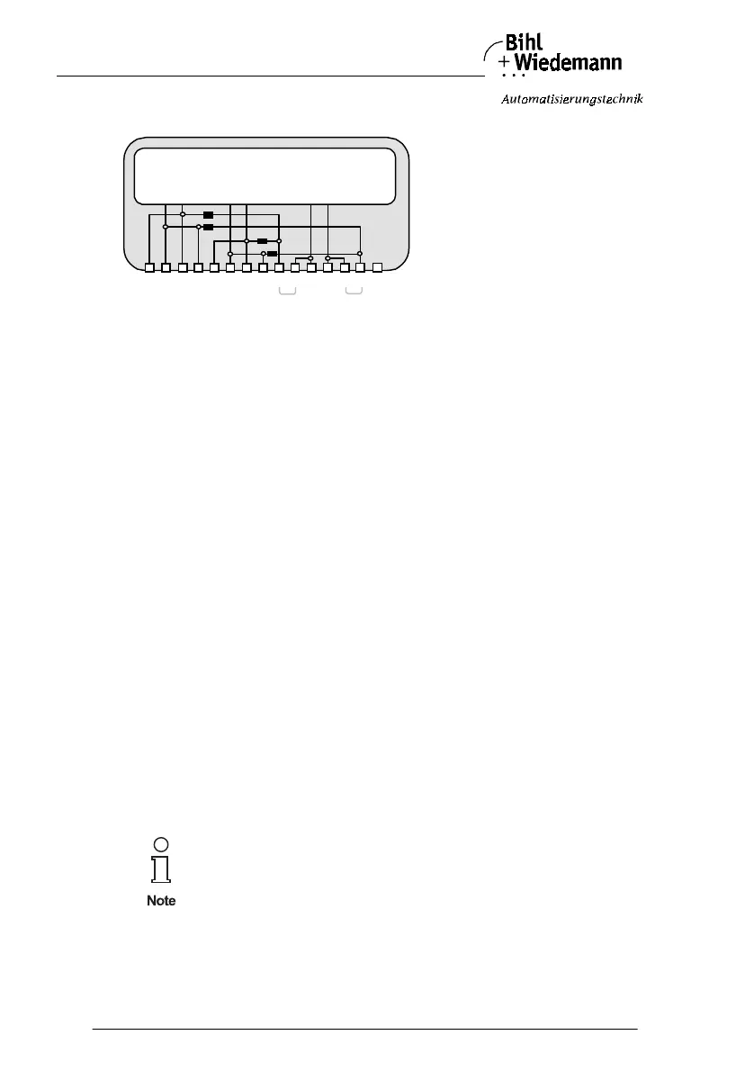
AS-i/PROFIBUS Gateway Connections, Displays and Operating Keys
Subject to reasonable modifications due to technical advances Copyright Bihl+Wiedemann, Printed in Germany
Bihl+Wiedemann GmbH · D-68199 Mannheim · Phone +49-621-339960 · Fax +49-621-3392239 · Internet http://www.bihl-wiedemann.de
issue date 7.1.2002
18
4.1.4 Double Master in IP20 with Power Supply N
The terminals have the following functions:
+ "AS-i +", Actuator Sensor Interface 1 or 2, positive terminal
These terminals are connected internally with point a2 of jumper "J+".
- "AS-i -", Actuator Sensor Interface 1 or 2, negative terminal
These terminals are connected internally with point b2 of jumper "J-".
24V Master power supply, positive terminal (18 - 31.6 V DC)
0V Master power supply, negative terminal
GND Ground terminal, used for better EMC.
Should be connected with a short wire to machine GND.
J+, J- Jumpers for selecting the power supply of AS-i
jumpers closed:
The AS-i circuits are powered by the master power supply.
Master power supply and AS-i network are then decoupled with coils.
jumpers open:
With the jumpers open (or missing), the AS-i master must be powered
by a separate AS-i power supply.
The AS-i power supply can be either connected to the jumper terminals
or to the AS-i line in the field.
Operation without AS-i power supply
When the jumpers are closed, the AS-i networks are powered by the master's po-
wer supply. For test purposes, it is possible to use a conventional 24 V DC power
supply to supply the AS-i network. You get optimum results with a 30 V DC voltage
source.
This variant requires only one power supply for 2 AS-i circuits!
AS-i Master
AS-i 1
power
GND a2 a1 24V
0V
+ -
J+
J-
b1b2
+ -
+ -
+ -
AS-i 2
 Loading...