AS-i/PROFIBUS Gateway Connections, Displays and Operating Keys
Subject to reasonable modifications due to technical advances Copyright Bihl+Wiedemann, Printed in Germany
Bihl+Wiedemann GmbH · D-68199 Mannheim · Phone +49-621-339960 · Fax +49-621-3392239 · Internet http://www.bihl-wiedemann.de
issue date 7.1.2002
24
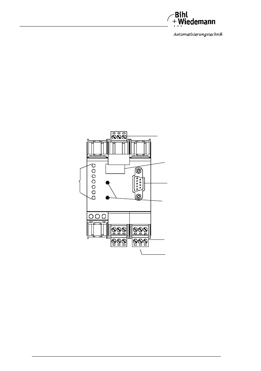
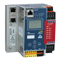
4.4 AS-i/PROFIBUS-DP gateway in KF-Housing
4.4.1 Device Schematics
The following are found on the front of the AS-i/PROFIBUS Gateway (see diagram
below):
1. Connection terminals for the AS-i circuit, also used for the power supply
2. A nine pin SUB-D connector as a PROFIBUS-serial interface,
3. 7 LEDs
4. A four position, seven section display for indicating the gateway's operating sta-
tus
5. 2 buttons for projecting the gateway
6. A rotary switch for bus termination..
1
19
28
20
21
29
30 31 32
33 34 35 36
22 23 24 25
26
27
PROFIBUS
12 3
7
8
9
POWER
SER AKTIV
CONFIG ERR
U ASI
ASI A KTIV
PRG ENABLE
PRJ MODE
5
3
4
2
1
6