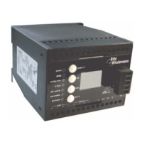
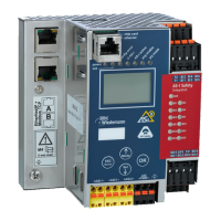
AS-i/PROFIBUS Gateway Connections, Displays and Operating Keys
Subject to reasonable modifications due to technical advances Copyright Bihl+Wiedemann, Printed in Germany
Bihl+Wiedemann GmbH · D-68199 Mannheim · Phone +49-621-339960 · Fax +49-621-3392239 · Internet http://www.bihl-wiedemann.de
issue date 7.1.2002
26
The two buttons have the following functions:
mode Used to switch between the projection mode and the protected operating
mode and to store the actual AS-i configuration as the reference configura-
tion.
set Selection and storage of an AS-i slave address.
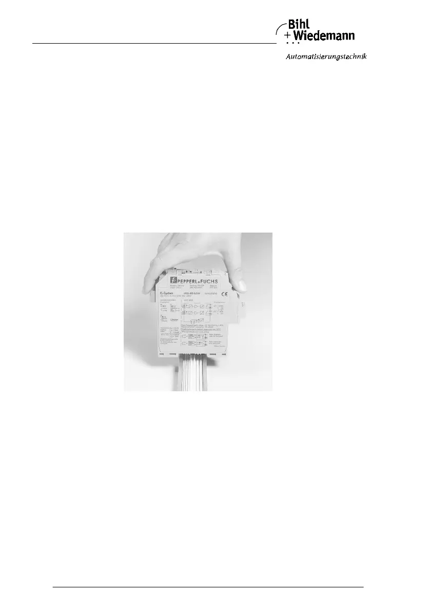
4.4.3 Mounting and Connections
4.4.3.1 Mounting
The KF… design of the gateway can be mounted on a 35 mm DIN rail in accor-
dance with EN 50022 and facilitates electrical connection through the “Power
Rail”. It is also possible to use the more conventional and expensive method of ca-
ble connections to terminals with this design.
The gateway is snapped directly onto the DIN rail. When using the power rail, an
electrical connection is automatically made (to the AS-i Bus) by snapping the ga-
teway onto the rail leads.
Connection via the Power Rail
The PR-05 power rail is an insert for the DIN rail in accordance with EN 50 022.
The UPR-05 is delivered with the appropriate DIN rail.
The 5 pin version of the power rail must be used during the establishment of AS-
Interface circuits. Two of the five power rails make up the AS-i bus.