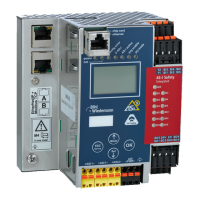
AS-i/PROFIBUS Gateway Connections, Displays and Operating Keys
Subject to reasonable modifications due to technical advances Copyright Bihl+Wiedemann, Printed in Germany
Bihl+Wiedemann GmbH · D-68199 Mannheim · Phone +49-621-339960 · Fax +49-621-3392239 · Internet http://www.bihl-wiedemann.de
issue date 7.1.2002
20
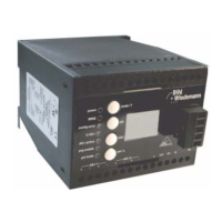
Do not try to provide the AS-i double master with power supply N with one AS-i
power supply each AS-i circuit, because the additional decoupling coils would bur-
den the AS-i line and cause erroneous AS-i telegrams.
4.2 The PROFIBUS Interface
4.2.1 Devices in IP20
The PROFIBUS interface is realized as a 9-pin SUB-D connector, in accordance
to the standard for PROFIBUS DIN 19245. It is placed on the right hand side of the
front panel.
In the wiring schemes above the current through the AS-i mas-
ter must not exceed 2.8 A each AS-i circuit.
-
power
supply
-
+
AS-i Slave
-
+
AS-i Slave
-
+
-
+
Master
power
suppl
AS-i Master
AS-i 1
power
AS-i 2
a1 a2
b2 0V b1 GND 24V + - +
-
+ -
+ -
S-i
power
supply
-
+
5
4
3
2
1
9
8
7
6
RxD/TxD-P
(data line B)
RxD/TxD-N
(data line A)
PROFIBUS