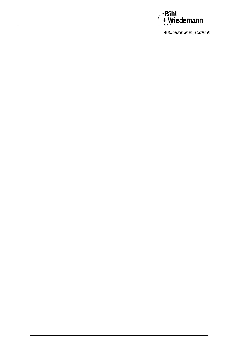
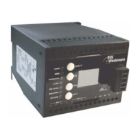
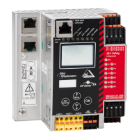
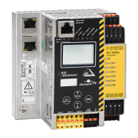
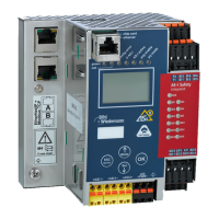
AS-i/PROFIBUS Gateway Connections, Displays and Operating Keys
Subject to reasonable modifications due to technical advances Copyright Bihl+Wiedemann, Printed in Germany
Bihl+Wiedemann GmbH · D-68199 Mannheim · Phone +49-621-339960 · Fax +49-621-3392239 · Internet http://www.bihl-wiedemann.de
issue date 7.1.2002
28
terminals. The RxD/TxD-P signal (B cable per PROFIBUS specifications) is assi-
gned to pin 3 and to terminal 25. The RxD/TxD-N signal (A cable per PROFIBUS
specifications) is assigned to pin 8 and to terminal 26.
In order to prevent equalizing currents, the interface cable's shielding is connected
with the gateway's grounding clamp through a capacitor. Otherwise, it should be
galvanically grounded.
4.4.4.1 Bus Termination Resistors
If the AS-i/PROFIBUS gateway is at the end of the PROFIBUS line, turn the rotary
switch under terminal 34 and 35 with a screwdriver clockwise for approximately 60
degrees to terminate the bus with the built-in termination resistors.
If the gateway is not at the end of the line, switch off the termination resistors by
turning the rotary switch counter-clockwise for approx. 60 degrees.
4.5 Factory-Reset
With factory reset the AS-i master is set to the factory default settings. All non vo-
latile stored data - e.g. the AS-i configutration - will be erased.
To reset the AS-i master to factory default settings both buttons have to be pres-
sed until the "88" in the display disappears while powering up the AS-i master.