AS-i/PROFIBUS Gateway Connections, Displays and Operating Keys
Subject to reasonable modifications due to technical advances Copyright Bihl+Wiedemann, Printed in Germany
Bihl+Wiedemann GmbH · D-68199 Mannheim · Phone +49-621-339960 · Fax +49-621-3392239 · Internet http://www.bihl-wiedemann.de
issue date 7.1.2002
21
The AS-i/PROFIBUS gateway sends and receives on pins 3 and 8 of the SUB-D
socket. The PROFIBUS signal “RxD/TxD-N (data line A)
1
” lies on pin 8, the signal
“RxD/TxD-P (data line B)
1
” lies on pin 3.
The pins 5 (0 V) and 6 (5 V) supply 5 V DC for the bus termination.
4.2.1.1 Bus termination
If the AS-i/PROFIBUS gateway is at the end of the PROFIBUS line, the termination
resistors in the PROFIBUS connector have to be switched on.
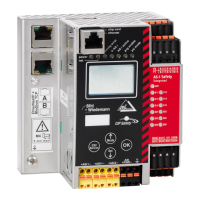
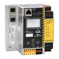
4.2.2 Devices in IP65
The AS-i/PROFIBUS gateway in IP65 can be connected to PROFIBUS with cage
clamp terminals inside of the device. For that purpose the top of the housing has
to be screwed off.
You can use a SUB-D data cable as an accessory part for AS-i masters in IP65
(art.-no. 1097) which is led through the heavy gauge terminals and is connected
after the following colour scheme:
3 - green, 4 - yellow, 5 - blue, 10 - red
The device in IP65 is powered out of the AS-i line to which it is connected by the
electromechanical interface (penetration technique as it is used with AS-i slaves).
4.2.2.1 Bus Termination
If the AS-i/PROFIBUS gateway is at the end of the PROFIBUS line, both DIP-swit-
ches have to be switched on to terminate the bus with the built-in termination resi-
stors.
If the gateway is not at the end of the line, swith off both DIP switches.
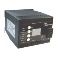
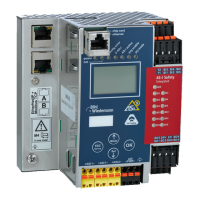
4.3 Display and Operating Elements
On the front panel of the AS-i/PROFIBUS gateway are seven light-emitting diodes,
a two-digit display and two push buttons.
With the devices in IP65 the push buttons are situated inside of the housing to avo-
id liquids from entering. The top of the housing has to be screwed off to operate
these push buttons.
1. If you measure the DC voltage between RxD/TxD-P (data line B) and RxD/TxD-N (data line A), RxD/TxD-P (data line B) is the positive pole
when the bus is silent.
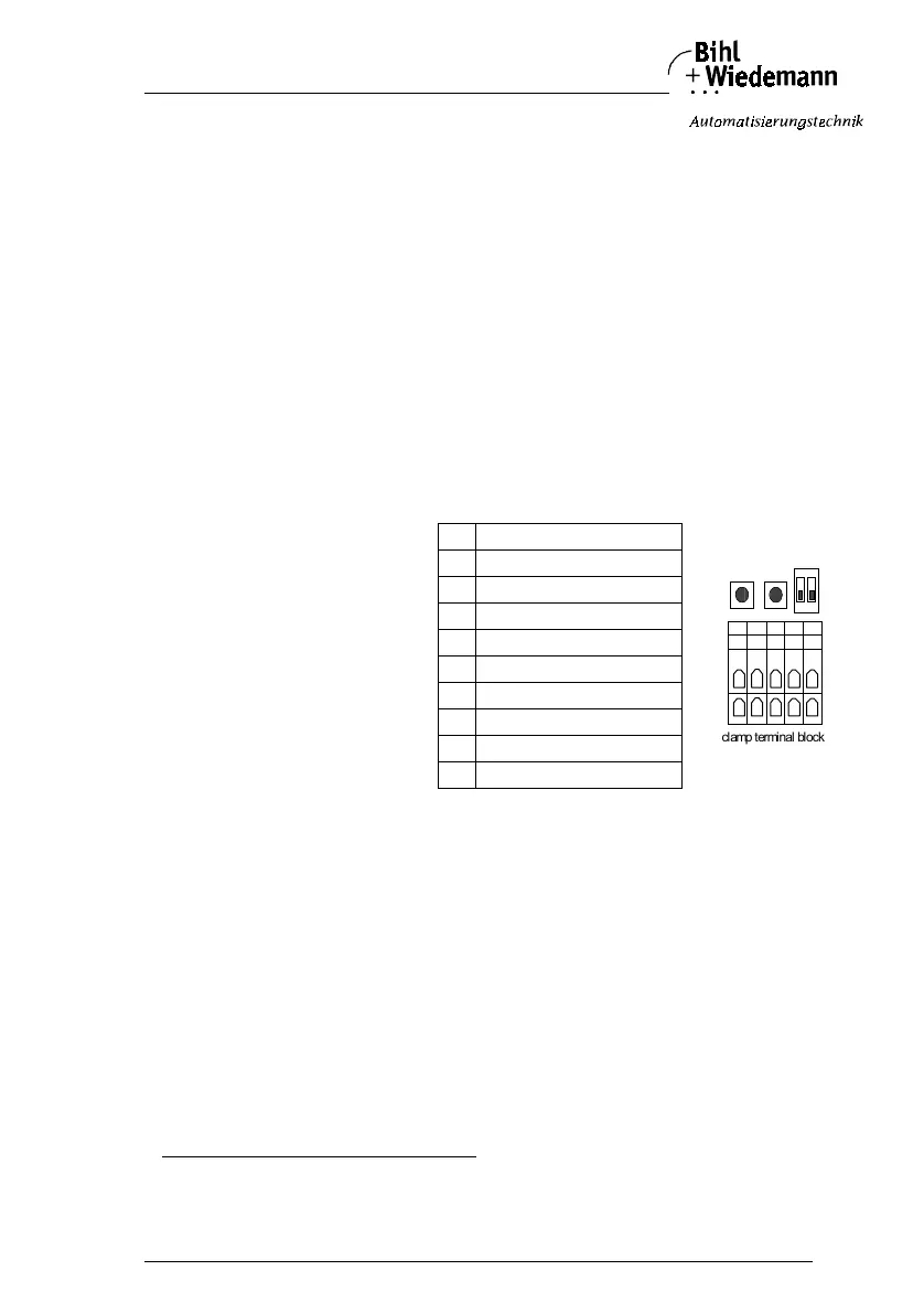
Connection of PROFI-
BUS
interface on cage clamp
terminal block and
arrangement on circuit
board:
1 RxD/TxD-N (data line A)
2 RxD/TxD-P (data line B)
3 RxD/TxD-N (data line A)
4 RxD/TxD-P (data line B)
50 V
6 Shield
7 FG function ground
8 FG function ground
9 Shield
10 +5 V
10 6 7 8 9
1 2 3 5 4
clamp terminal block
buttons
DIP switches
off