43
Chapter 5 - NESS H200 Wireless Clinician's Kit
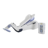
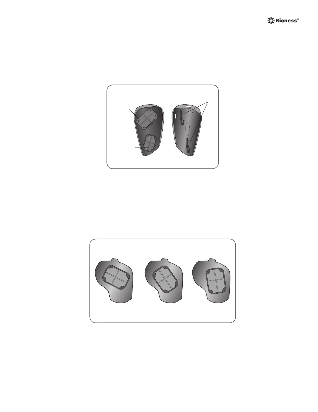
Front Back
ED #1
Electrode
Base
EPB #2
Electrode
Base
Conducting
Springs
Figure 5-9: Right (Rt) extensor fitting panel, front and back.
Each extensor fitting panel has two electrode bases (Extensor Digitorum (ED) #1 and
Extensor Pollicis Brevis (EPB) #2) on one side and two conducting springs on the other side.
See Figure 5-9. The conducting springs make electrical contact with the #1 and #2 electrode
base sockets on the Orthosis.
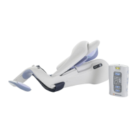
BA C
Flexor Fitting Panels
The flexor fitting panels are available in right (Rt) and left (Lt) configurations, in three electrode
base configurations: A, B, and C. See Figure 5-10.
Figure 5-10: Flexor fitting panels A, B, and C: right (Rt) configuration.
The flexor fitting panels have one electrode base (Flexor Digitorum Superficialis (FDS) #4)
and one conducting spring each. The conducting spring is on the back of the fitting panel and
makes contact with the #4 electrode base socket on the Orthosis.
 Loading...