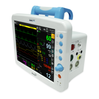
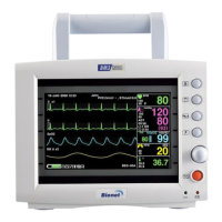
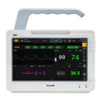
Rev. 3.1 1.BASIC
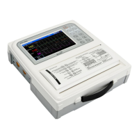
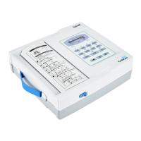
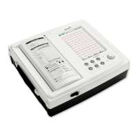
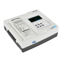
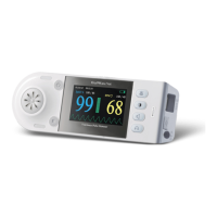
BM5 (CS,CX) User’s Manual
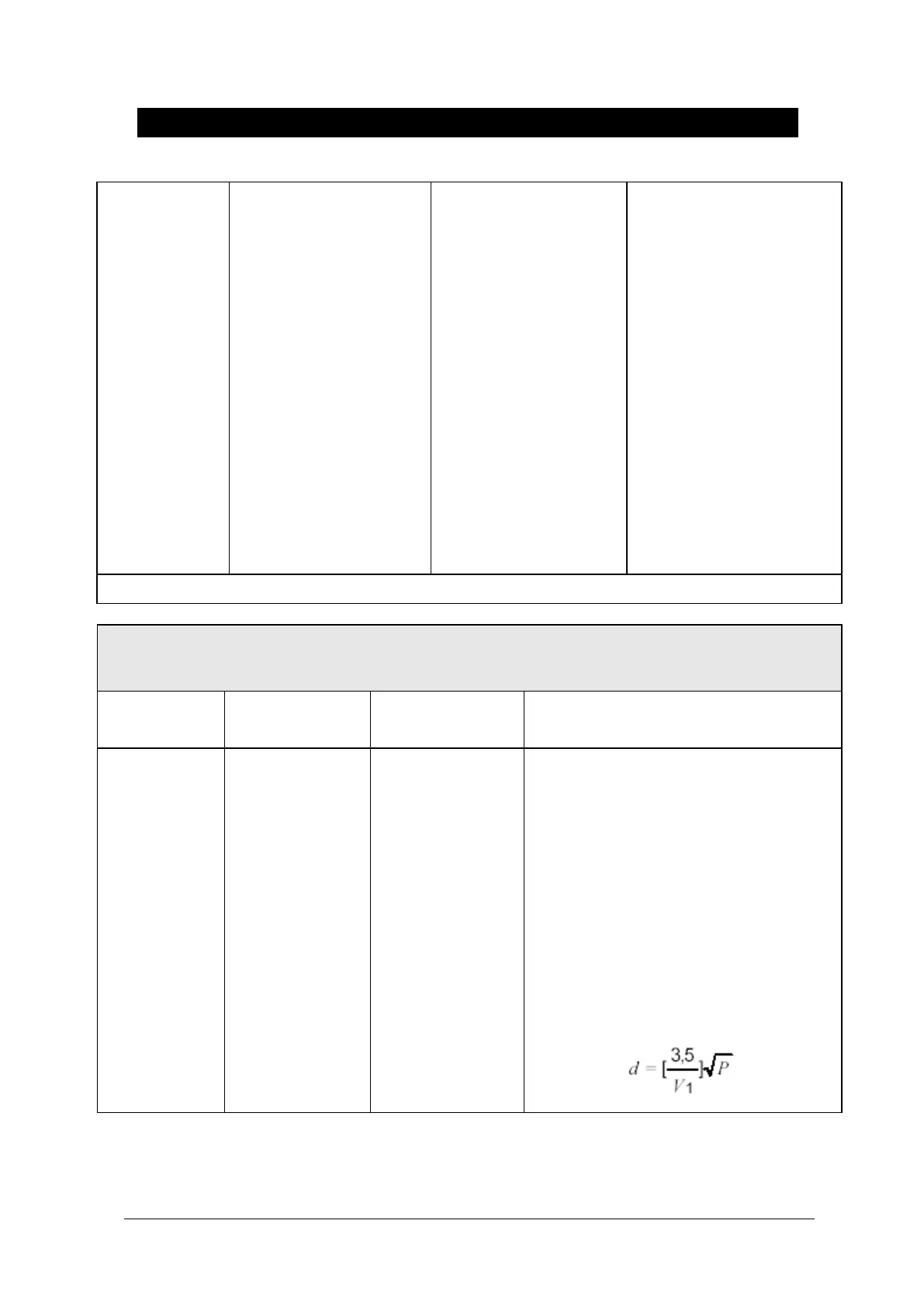
Voltage dips, s
hort
Interruptions an
d
Voltage variatio
ns
on power suppl
y
input lines
IEC 61000-4-1
1
<5%
U
т (>95% dip in
U
т)
for 0.5cycle
40%
U
т (60% dip in
U
т
)
for 5 cycle
70%
U
т (30% dip in
U
т)
for 25 cycle
<5%
U
т (<95% dip in
U
т
)
for 5 s
<5%
U
т (>95% dip in
U
т)
for 0.5cycle
40%
U
т (60% dip in
U
т
)
for 5 cycle
70%
U
т (30% dip in
U
т)
for 25 cycle
<5%
U
т (<95% dip in
U
т )
for 5 s
Mains power quality shoul
d be that of a typical com
mercial or hospital environ
ment. If the user of the
BM5 system requires conti
nued operation during pow
er mains interruptions, it i
s recommended that the
BM5 system be powered fr
om an uninterruptible pow
er supply or a battery
Note:
U
т is the a.c. mains voltage prior to application of the test level.
The BM5 system is intended for use in the electromagnetic environment specified below.
The customer or the user of the BM5 system should assure that it is used in such an environment
Electromagnetic environment -guidance
Conducted RF
IEC 61000-4-
6
Portable and mobile RF communications
equipment should be used no closer to
any part of the BM5 system, including
cables, than the recommended separati
on distance calculated from the equatio
n applicable to the frequency of the tra
nsmitter.
Recommended separation distance