99
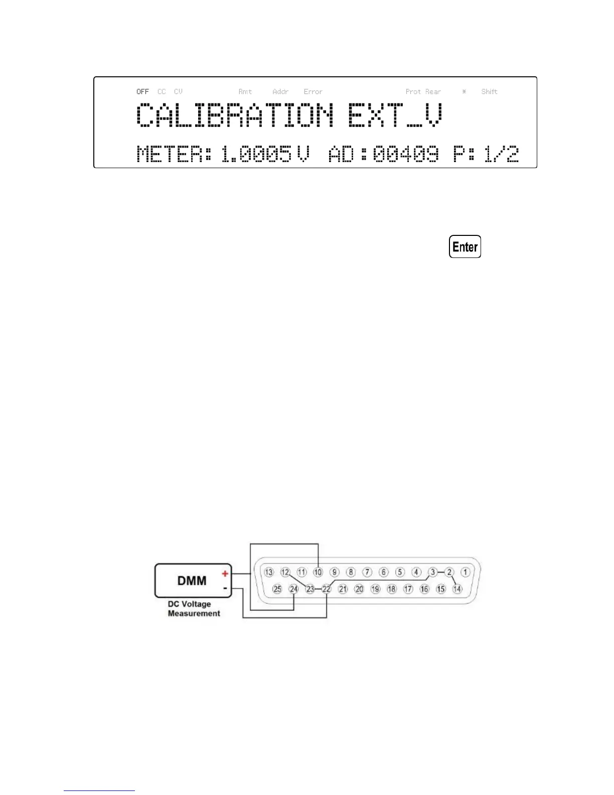
The P: 1/2 signifies there are 2 points to be calibrated and the
current calibration point is 1.
3. Input the voltage reading from the DMM in the METER
parameter by using the numeric keypad and press .
4. Repeat this procedure by entering the meter readings for points
2.
5.6 External Current Programming
Calibration
Follow the steps below to perform the external current programming
calibration:
1. Connect the DMM to the external analog control terminals of
DB25 connector (+ on the DMM to Pins 10 and 24, - on the
DMM to Pin 22(GND)) on the rear of the power supply, as shown
in the figure below:
Figure 5.5 – External Current Programming Calibration Diagram