APPENDIX I: SERVSWITCH™ MEDIA EXTENDER
159
I.5. Setup at the Local Unit
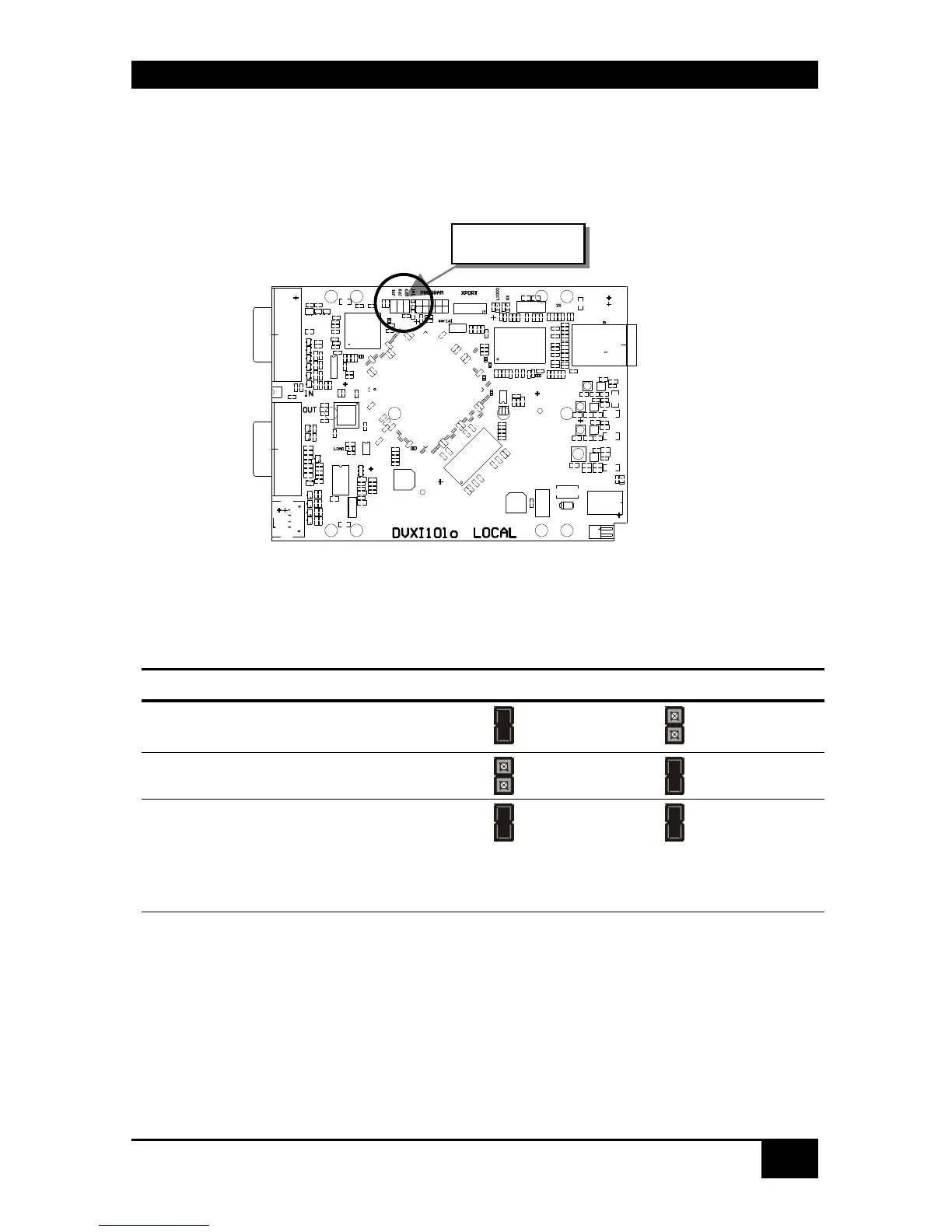
After unscrewing and opening the upper shell, please place the device with the CATx-
connectors to the right and the monitor connectors to the left.
The main PCB then will look like this:
Use the diagram to locate jumpers.
DDC / colour depth
You can select, whether the DDC information is taken from internal DDC table, from the
local monitor or downloaded from the remote monitor and stored in internal table.
DDC JP1 JP2
From internal table
(default)
From local monitor
Loading the DDC information from the
remote monitor into the internal DDC
table (see also below: loading the DDC
information from the remote monitor into
the internal DDC table)
JP1, JP2, JP3