3.22.3 Piping connections
Connect the piping between the photohelic switch/gauge and the iH exhaust enclosure using
the following steps:
1. Connect the male connector to the photohelic monitoring port on the photohelic spoolpiece
(Figure 3-15, item 2). Refer to Section 6.2 for guidelines.
2. See Figure 3-16. Connect the braided hose to the male connector and gasket (1) on the
photohelic spoolpiece and to the photohelic gauge port as shown. (See Section 6.2 for
guidelines)
iH Dry Pumping Systems 3-39
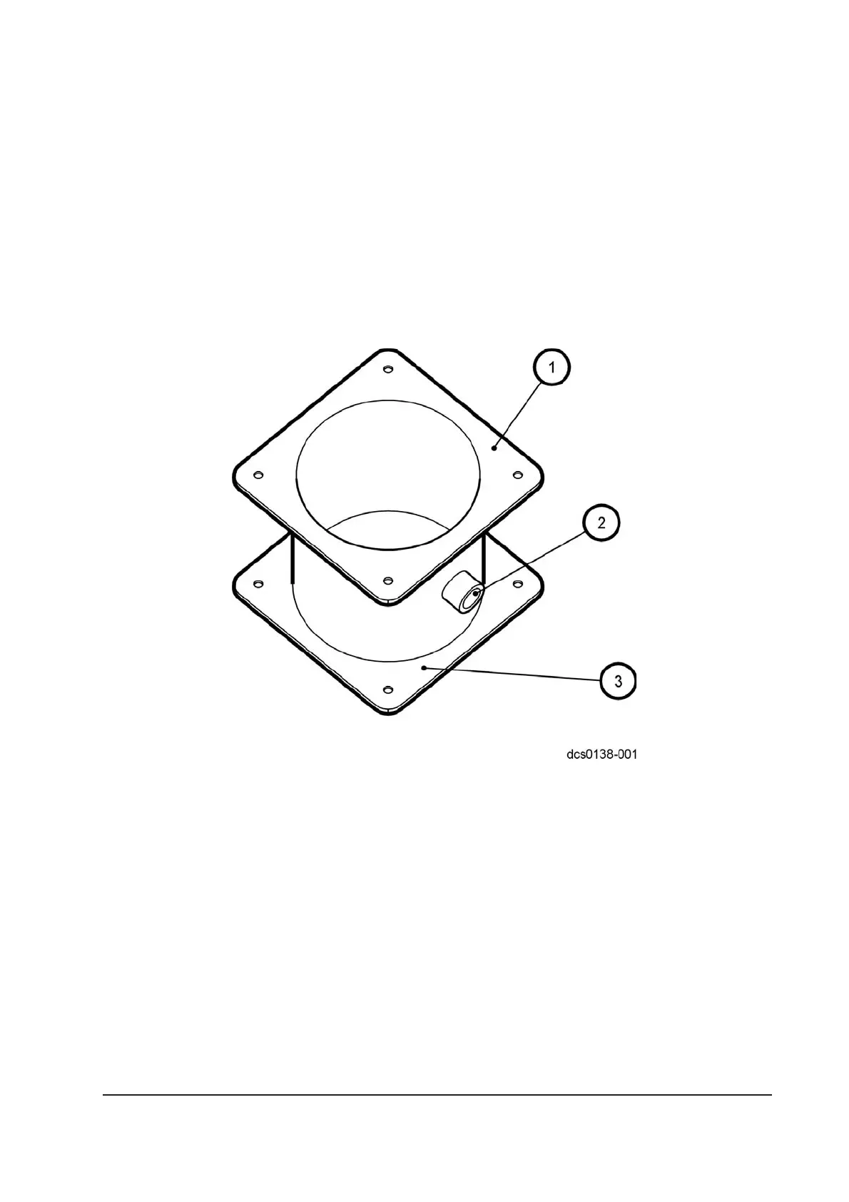
Figure 3-15 - Photohelic spoolpiece
1. Outlet to be connected to factory extraction system
2. Photohelic monitoring port
3. Inlet to be connected to pump enclosure extraction port
 Loading...


