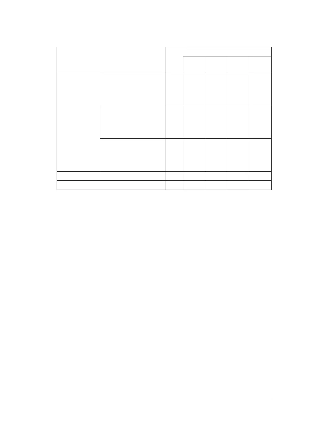
Parameter Unit ✝
Default setpoint values
Low
alarm
Low
warning
High
warning
High
alarm
Total nitrogen
flow
(high gas
configuration:
factory set)
Shaft-seals purge on,
Exhaust-purge on,
2/3-interstage purge off,
3/4-interstage purge off,
Inlet-purge off
slm ADJ 3 18 ADJ
Shaft-seal purge on,
Exhaust-purge on,
2/3-interstage purge on,
3/4-interstage purge on,
Inlet-purge off
slm ADJ 38.0 59.4 ADJ
Shaft-seal purge on,
Exhaust-purge on,
2/3-interstage purge on,
3/4-interstage purge on,
Inlet-purge on
slm ADJ 38.0 60.0 ADJ
Exhaust pressure psig ADJ ADJ 5.0 8.0
Shaft-seals purge pressure psig ADJ ADJ 12.5 ADJ
✝ Only slm gas flow values are given in the table, because only slm values can be entered in the
Pump Display Terminal. To convert slm values to Pa.ls
-1
, multiply by (1.013 /60) x 10
5
.
Table 2-6 - Gas module default setpoints: high gas configuration
2.12 Connections
Inlet and outlet See Table 2-1
Electrical supply connector
Type Harting HAN-K-4/2
Cable outside diameter range 18 to 27 mm
Maximum conductor cross-sectional area 16 mm
2
Pump Display Module connector XLR type 4-way
Network communications connector XLR type 4-way
Exhaust Gas Management interface 6-pin DIN [3-Common; 4-Normally
Closed; 5-Normally Open]
iH Tool Interface Module connector XLR type 6-way
Nitrogen supply connector
1
/
4
inch Tube fitting
Water inlet connector *
3
/
8
inch BSP male quick-disconnect
Water outlet connector *
3
/
8
inch BSP female quick-disconnect
Active gauge connector SCC68 socket
Pump Display Terminal connector RJ12
Tool interface adaptor (iTIM) 15-way D-type
* Connector mating-halves to connect your cooling-water supply and return pipes are supplied with the
iH system: refer to Section 3.18.
2-18 iH Dry Pumping Systems