3.22.4 Cable connections
Connect the cabling between the photohelic switch/gauge and the disconnect box as follows:
1. Using a flat screwdriver, open the disconnect door by turning the lock.
2. Ensure power to the disconnect box is isolated and that CB1 is open.
3. Punch out the photohelic gauge signal and power cable holes on the bottom of the
disconnect box (Items 4 and 5 on Figure 3-14)
4. Connect the photohelic switch/gauge signal cable to terminals 5 and 6 (See Figures 3-12 and
3-13)
5. Connect the photohelic switch/gauge power cable to CB1, the Neutral Terminal and the
Ground Bar. (See Figures 3-12 and 3-13)
6. Restore power to the disconnect box and close CB1
7. Using a flat screwdriver, secure the disconnect door by turning the lock
3-40 iH Dry Pumping Systems
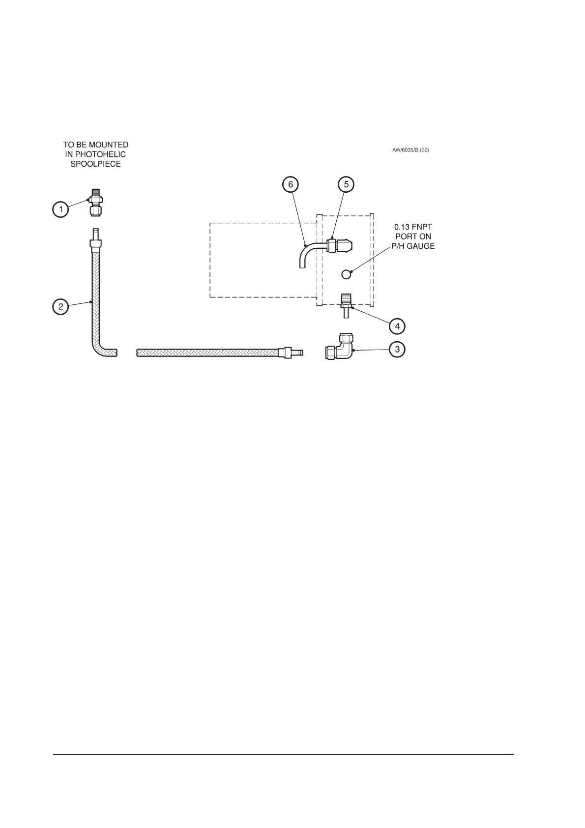
1. Male connector
and gasket
2. Braided hose
3. Elbow union
4. Male adapter
5. Male elbow
6. Reference tube
Figure 3-16 - Photohelic gauge piping connections


 To Next Page