iH Dry Pumping System 1-7
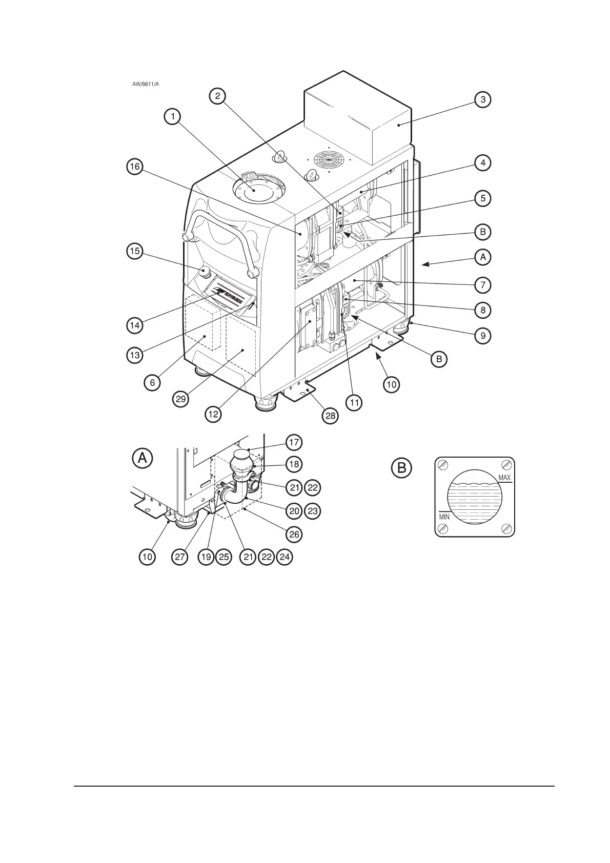
Figure 1-1 - The iH system (iH1000 shown, with side panels removed)
1. Inlet
2. HCMB oil filler-plug *
3. Inverter enclosure
✝
4. HCMB pump-motor *
5. HCMB oil-level sight-glass *
6. Gas Module
7. HCDP pump-motor
8. HCDP oil filler-plug
9. Levelling-foot
10. Castor
11. HCDP oil-level sight-glass
12. HCDP pump
20. Elbow
21. NW40 trapped ‘O’ ring
22. NW40 clamping ring
23. Elbow insulation jacket
24. Clamps insulation jacket
25. Exhaust pipe insulation
jacket
26. Exhaust enclosure
27. Drip tray
28. Seismic bracket
29. Electronics Module
13. Nitrogen pressure regulator
14. Pump Display Terminal
15. Emergency stop switch
16. HCMB pump *
17. Outlet
18. Check-valve
19. Exhaust-pipe
* iH600/iH1000 only
✝ iH1000 onlyInlet