iH Dry Pumping Systems 1-17
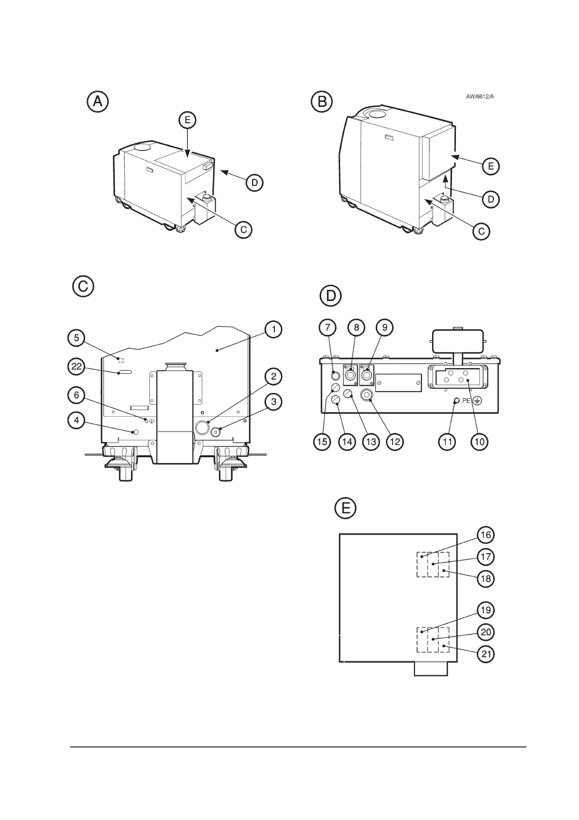
16. Fuse F6
17. Fuse F5
18. Fuse F4
19. Fuse F1
20. Fuse F2
21. Fuse F3
22. iTIM connector
Figure 1-5 - Services and electrical connections on the rear of the iH system
1. Rear cover
2. Cooling-water outlet
3. Cooling-water inlet
4. Nitrogen inlet
5. Position of Active Gauge connector
6. RF earth (ground) stud
7. Power on lamp
8. Tool Interface Module connector
9. LON interface connector
10. Electrical supply connector
11. Protective earth (ground) stud
12. Exhaust Gas Management interface
13. d.c. electrical supply fuse holder (F7)
14. Emergency stop fuse holder (F9)
15. Tool Interface Module fuse holder (F8)
A iH80
B iH600/iH1000
C Rear panel
D, E Detail of Electrics box
 Loading...


