Operating Instructions ACTIVE 06/07100
100 Operating Instructions ACTIVE 06/07
11.2.1 Switch-Off Threshold
The
Switch-off Threshold Stop Function 637 defines the frequency as from which a
standstill of the drive is recognized. This percentage parameter value is applied to the
set
Maximum Frequency 419.
The switch-off threshold is to be adjusted according to the load behavior of the drive
and the device output, as the drive must be controlled to a speed below the switch-off
threshold.
Parameter Settings
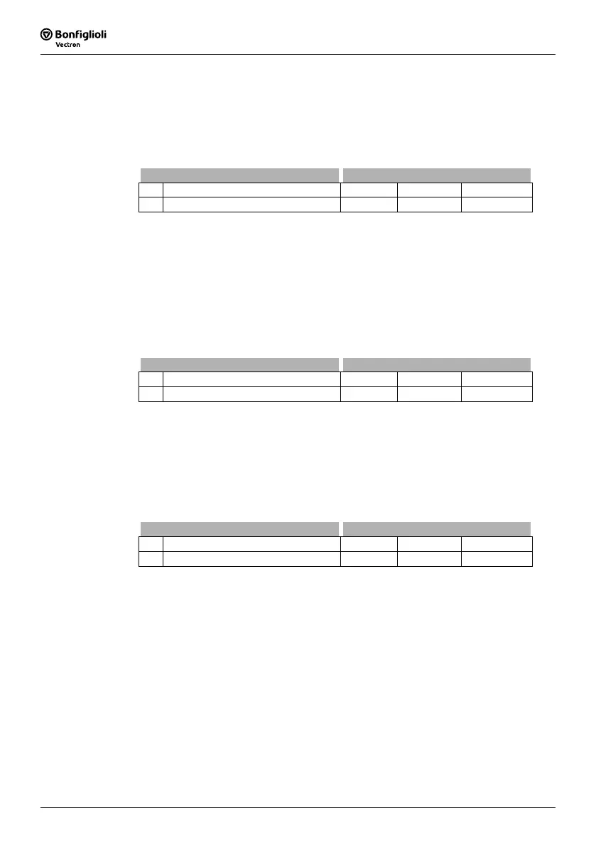
No. Description Min. Max. Fact. sett.
637 Switch-Off Threshold 0.0 % 100.0 % 1.0 %
Attention! If the motor builds up a stopping torque, it may be possible that the
switch-off threshold stop function is not reached due to the slip fre-
quency and the standstill of the drive is not recognized. In this case,
increase the value of the
Switch-off Threshold Stop Function 637.
11.2.2 Holding Time
The
Holding Time Stop Function 638 is considered in stopping behaviors 1, 3, 4 and
6. Controlling to zero speed results in the motor heating up and should only be done
for a short period in the case of internally ventilated motors.
Parameter Settings
No. Description Min. Max. Fact. sett.
638 Holding Time 0.0 s 200.0 s 1.0 s
11.3 Direct current brake
Stopping behaviors 3, 6, 7 and the search run function include the direct current brake.
Depending on the setting of the stop function, a direct current is impressed into the
motor either directly or, when it is at a standstill, after the demagnetization time. The
impression of the
Braking current 631 results in the motor heating up and should only
be done for a short period in the case of internally ventilated motors.
Parameter Settings
No. Description Min. Max. Fact. sett.
631 Braking Current 0.00 A √2⋅I
FIN
√2⋅I
FIN
The setting of the parameter
Braking Time 632 defines the time-controlled stopping
behavior. Contact-controlled operation of the direct current brake is activated by enter-
ing the value zero for the
Braking Time 632.
Time controlled:
The direct current brake is controlled by the status of signals Start clockwise and Start
anticlockwise. The current set by the parameter
Braking Current 631 flows until the
time set by the parameter
Braking Time 632 has expired. During the braking time the
status of both signals Start clockwise and Start anticlockwise are logical 0 (low) or
logical 1 (high).
 Loading...


