Operating Instructions ACTIVE 06/07128
128 Operating Instructions ACTIVE 06/07
14 Control Inputs and Outputs
The modular structure of the frequency inverters enables a wide spectrum of applica-
tions on the basis of the available hardware and software functionality. The control
inputs and outputs of terminals X210A and X210B described in the following can be
linked to software modules freely via the described parameters.
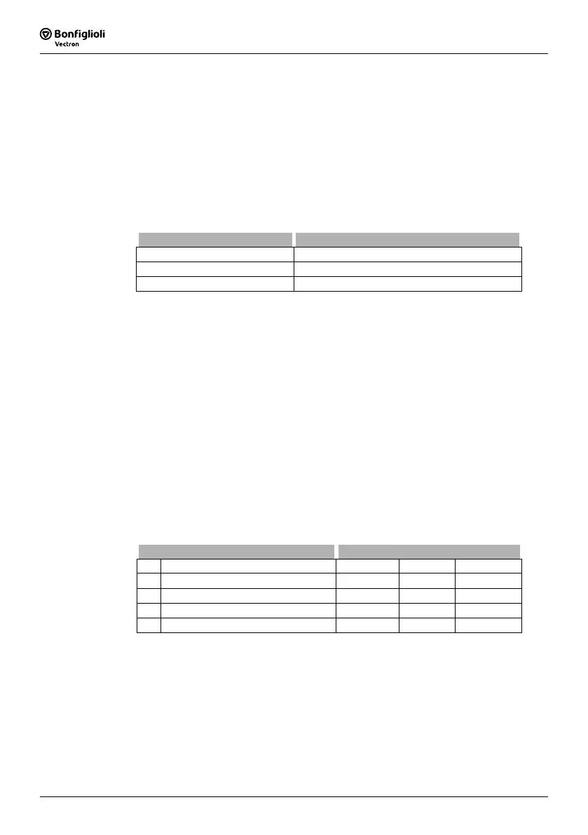
14.1 Multi-function input MFI1
Multifunction input MFI1 can either be configured as a voltage, current or a digital
input. Depending on the selected
Operation Mode 452 for the multifunction input, a
link to various functions of the software is possible. The unused operation modes are
assigned the signal value 0 (LOW).
Operation mode 452 Function
1 - Voltage Input voltage signal (MFI1A), 0 V ... 10 V
2 - Current Input current signal (MFI1A), 0 mA ... 20 mA
3 - Digital Input digital signal (MFI1D), 0 V ... 24 V
Note:
The sampling rate of multi-function input MFI1D is slower than that of
digital signals S1IND, S2IND, etc. For this reason, this input should only
be used for signals which are not time-critical.
14.1.1 Analog Input MFI1A
Multifunction input MFI1 is configured by default for an analog reference value source
with a voltage signal of 0 V to 10 V.
Alternatively, you can select the operation mode for an analog current signal of 0 mA
to 20 mA. The current signal is continuously monitored and the fault message "F1407"
displayed if the maximum figure is exceeded.
14.1.1.1 Characteristic
Mapping of the analog input signal onto a reference frequency value or a reference
percentage value is possible for various requirements. Parameterization can be done
via two points of the linear characteristic of the reference value channel.
Point 1 with coordinates X1 and Y1 and point 2 with coordinates X2 and Y2 can be set
in four data sets.
Parameter Settings
No. Description Min. Max. Fact. sett.
454 Point X1 0.00 % 100.00 % 2.00 %
455 Point Y1 -100.00 % 100.00 % 0.00 %
456 Point X2 0.00 % 100.00 % 98.00 %
457 Point Y2 -100.00 % 100.00 % 100.00 %
The coordinates of the points relate, as a percentage, to the analog signal with 10 V
or 20 mA and parameter
Maximum Frequency 419 or parameter Maximum Reference
Percentage
519. The direction of rotation can be changed via the digital inputs
and/or by selection of the points.
Attention!
The monitoring of the analog input signal via the parameter
Er-
ror/Warning Behavior
453 demands the examination of the parameter
Point X1 454.
 Loading...


