Operating Instructions ACTIVE06/07 49
06/07 Operating Instructions ACTIVE 49
5.6 Control Terminals
The control and software functionality can be freely configured to ensure a reliable
and economical operation. The operating instructions describe the factory settings of
the standard connections in the relevant
Configuration 30 as well as the software
parameters to be set up.
Caution! Switch off power supply before connecting or disconnecting the keyed
control inputs and outputs. Otherwise, components may be damaged.
• The unit may only be connected with the power supply switched off.
• Make sure that the frequency inverter is discharged.
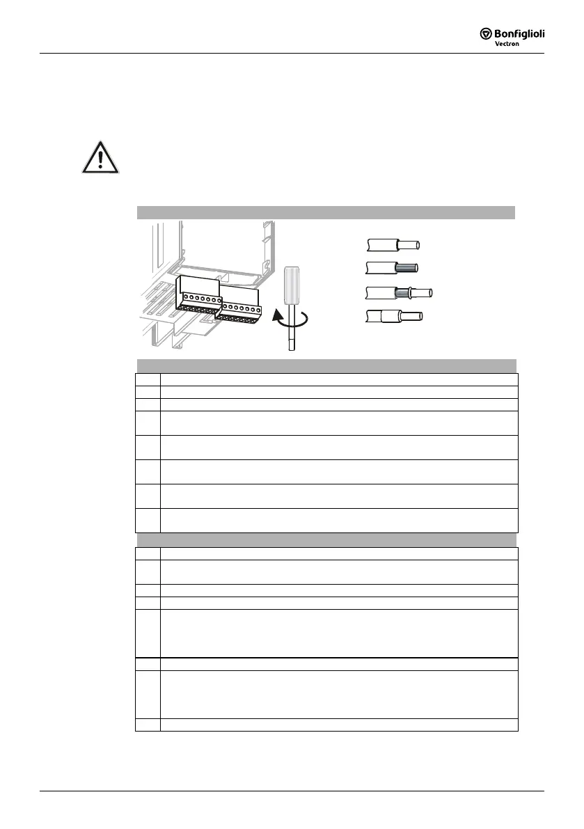
Control Terminals
0.14 … 1.5 mm
AWG 30 … 16
2
Wieland DST85 / RM3,5
0.14 … 1.5 mm
AWG 30 … 16
2
0.25 … 1.0 mm
AWG 22 … 18
2
0.25 … 0.75 mm
AWG 22 … 20
2
0.2 … 0.3 Nm
1.8 … 2.7 lb-in
Control terminal X210A
Ter. Description
1 Voltage output 20 V, I
max
=180 mA
1)
2 Ground / GND 20 V
3 Digital input S1IND, U
max
= DC 30 V, 10 mA at DC 24 V, PLC compatible,
response time approx. 16ms (on), 10 μs (off)
4 Digital input EM-S2IND, U
max
= DC 30 V, 10 mA at DC 24 V, PLC compatible,
response time approx. 16 ms
5 Digital input EM-S3IND, U
max
= DC 30 V, 10 mA at DC 24 V, PLC compatible,
response time approx. 16 ms
6 Digital input S4IND, U
max
= DC 30 V, 10 mA at DC 24 V, PLC compatible,
frequency signal: 0...30 V, 10 mA at 24 V, f
max
= 150 kHz
7 Digital input S5IND, U
max
= DC 30 V, 10 mA at DC 24 V, PLC compatible,
frequency signal: 0...30 V, 10 mA at 24 V, f
max
= 150 kHz
Control terminal X210B
Ter. Description
1 Digital input S6IND, U
max
=30 V, 10 mA at 24 V, PLC compatible,
response time approx. 16 ms
2 Ground / GND 20 V
3 Digital output S1OUT, U= DC 24 V, I
max
=40 mA, overload and short-circuit proof
4 Multi-function output MFO1,
analog signal: U= DC 24 V, I
max
=40 mA, pulse-width modulated, f
PWM
=116 Hz
digital signal: U= DC 24 V, I
max
=40 mA, overload and short-circuit proof,
frequency signal: DC 0...24 V, I
max
=40 mA, f
max
=150 kHz
5 Reference output DC 10 V, I
max
=4 mA
6 Multi-function input MFI1,
analog signal: resolution 12 Bit, DC 0... 10 V (Ri=70 kΩ), 0...20 mA (Ri=500 Ω),
digital signal: response time approx. 16 ms, U
max
= DC 30 V, 4 mA at DC 24 V,
PLC compatible
7 Ground / GND 10 V
1)
The power supply at terminal X210A.1 may be loaded with a maximum current of
I
max
= 180 mA. The maximum current available is reduced by the digital output
S1OUT and multifunctional output MFO1.
 Loading...


