Operating Instructions ACTIVE 06/0734
34 Operating Instructions ACTIVE 06/07
5.3 Optional Components
Thanks to the modular hardware components, the frequency inverters can be inte-
grated in the automation concept easily. The standard and optional modules are rec-
ognized during the initialization, and the controller functionality is adjusted automati-
cally. For the information required for installation and handling of the optional mod-
ules, refer to the corresponding documentation.
Danger! The hardware modules at slots B and C may only be assembled and dis-
assembled after the frequency inverter has been disconnected safely from
power supply. Wait for some minutes until the DC link capacitors have
discharged before starting the work.
• The unit may only be connected with the power supply switched off.
• Make sure that the frequency inverter is discharged.
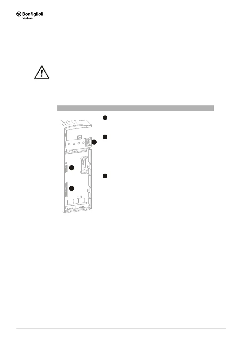
Hardware modules
A
Control Unit KP500
Connection of the optional control unit KP500 or an interface
adapter KP232.
B
Communication module CM
Plug-in section for connection to various communication pro-
tocols:
− CM-232: RS232 interface
− CM-485: RS485 interface
− CM-PDP: Profibus-DP interface
− CM-CAN: CANopen interface
C
Expansion module EM
A
B
C
Slot for customer-specific adaptation of the control inputs
and outputs to various applications:
− EM-ENC: extended speed sensor evaluation
− EM-RES: resolver evaluation
− EM-IO: analog and digital inputs and outputs
− EM-SYS: system-bus
(system bus in combination with CM-CAN communication
module upon request)
Attention! If two optional components with CAN-Protocol controller are installed,
the system-bus interface in the EM expansion module is deactivated!
 Loading...


