Operating Instructions ACTIVE 06/0778
78 Operating Instructions ACTIVE 06/07
7.2.7.2 Set points at multi-functional input
The multi-functional input MFI1 can be parameterized for a reference value signal in
Operation mode 452. Operation mode 3 should only be selected by expert users for
drive control via
Fixed frequency 1 480 and Fixed frequency 2 481.
Operation mode 452 Function
1 - Voltage Input Voltage signal (MFI1A), 0V ... 10V
2 - Current Input Current signal (MFI1A), 0mA ... 20mA
3 - Digital Input Digital signal (MFI1D), 0V ...24V
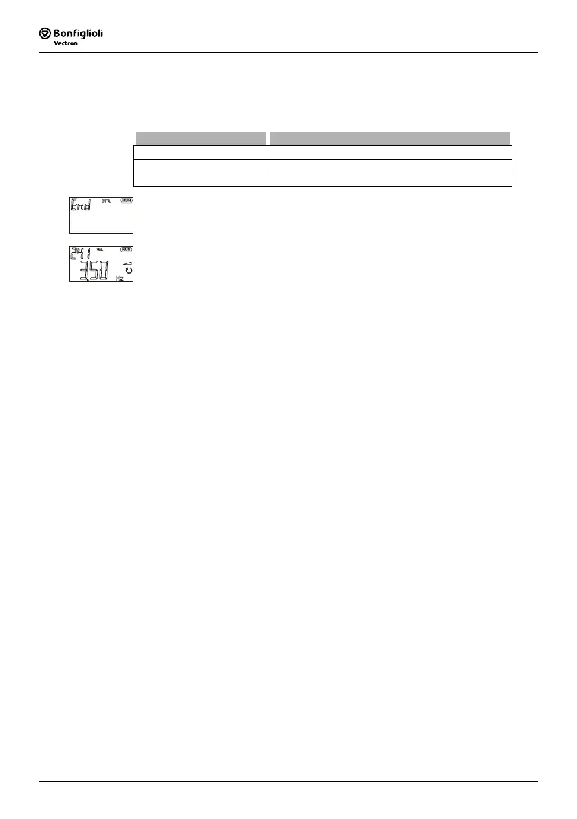
• Confirm the "End" display by pressing the ENT key.
The guided commissioning of the frequency inverter is terminated via a reset and the
initialization of the frequency inverter. The relay output X10 signals a fault.
After successful initialization of the frequency inverter, the factory-set parameter Ac-
tual frequency
241 is displayed. If a signal is present at digital inputs S1IND (control-
ler release) and S2IND (start clockwise operation) or at digital inputs S1IND (control-
ler release) and S3IND (start of anti-clockwise operation), the drive is accelerated to
the adjusted
minimum frequency 418 (default values: 3.50 Hz in configurations 110,
111, 410, 411, 430 and 0.00 Hz in configurations 210, 211, 230).
7.2.7.3 Selection of an actual value for display
After commissioning, the value of parameter Actual frequency 241 is displayed at the
control unit KP500.
If another actual value is to be displayed after a restart, make the following settings:
• Use the arrow keys to select the actual value to be displayed as from now.
• Use the ENT key to display the value of the parameter.
• Press the ENT key again. "SEt" is displayed for confirmation.
As from now, the selected actual value is displayed after each restart.
If the parameter settings were made via the optional control software or in the PARA
menu branch of the control unit, the display of the selected actual value must be acti-
vated manually. Use the ESC key to switch to the selection of the actual value for
display again.
 Loading...


