Operating Instructions ACTIVE06/07 77
06/07 Operating Instructions ACTIVE 77
After completion or during the parameter identification, error messages may be dis-
played. Depending on the error code, the following instructions should be followed
and the measures indicated should be taken.
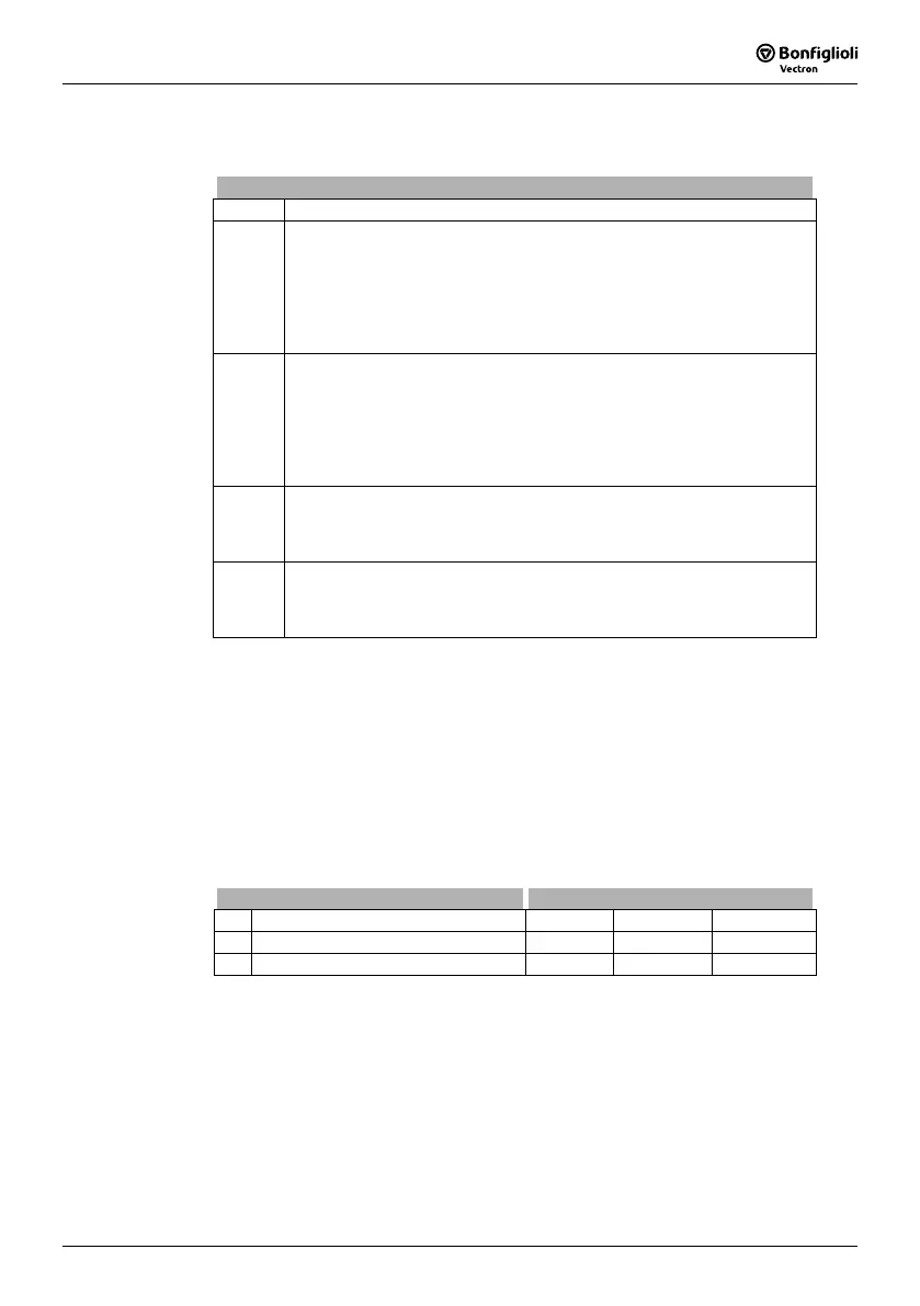
Error Messages
Code Measures / Remedy
SF0011 The main inductance measurement has failed because the motor has a
high slip. Correct the rated motor values in parameters 370, 371, 372,
374, 375 and 376. Carry out the guided commissioning once again. In
case an error message is displayed again, enter the value 110 for parame-
ter
Configuration 30 (sensorless regulation according to U/f-characteristic)
if value 410 was set so far. Carry out the guided commissioning once
again.
SF0012 The leakage inductance measurement has failed because the motor has a
high slip. Correct the rated motor values in parameters 370, 371, 372,
374, 375 and 376. Carry out the guided commissioning once again. In
case an error message is displayed again, enter the value 110 for parame-
ter
Configuration 30 (sensorless regulation according to U/f-characteristic)
if value 410 was set so far. Carry out the guided commissioning once
again.
SF0021 The measurement of the stator resistance did not deliver a plausible value.
Check the cables at the terminals of the motor and the frequency inverter
for proper connection and check the contacts for corrosion and safe con-
tact. Repeat the parameter identification.
SF0022 The measurement of the rotor resistance did not deliver a plausible value.
Check the cables at the terminals of the motor and the frequency inverter
for proper connection and check the contacts for corrosion and safe con-
tact. Repeat the parameter identification.
7.2.7 Application data
Due to the wide range of drive applications with the resulting parameter settings it is
necessary to check further parameters. The parameters polled during the guided
commissioning procedure were selected from standard applications. After completion
of commissioning, further parameters can be set in the PARA menu branch.
7.2.7.1 Acceleration and deceleration
The settings define how fast the output frequency changes after a reference value
change or a start, stop or brake command.
Parameter Settings
No. Description Min. Max. Fact. sett.
420 Acceleration (Clockwise) 0.00 Hz/s 999.99 Hz/s 5.00 Hz/s
421 Deceleration (Clockwise) 0.00 Hz/s 999.99 Hz/s 5.00 Hz/s
Attention! The deceleration of the drive is monitored in the default parameter set-
ting
Voltage controller operation mode 670. The deceleration ramp can
be extended in the case of an increase in the DC link voltage during
regenerative operation and/or during the braking process.
 Loading...


