Operating Instructions ACTIVE06/07 199
06/07 Operating Instructions ACTIVE 199
19.2 Error Environment
The parameters of the error environment help troubleshooting both in the settings of
the frequency inverter and also in the complete application. The error environment
documents the operational behavior of the frequency inverter at the time of the last
four faults.
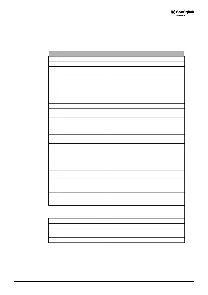
Error Environment
No. Description Function
330 DC link voltage Direct voltage in the DC link.
331 output voltage
Calculated output voltage (motor voltage) of the
frequency inverter.
332 Stator Frequency
The output frequency (motor frequency) of the
frequency inverter.
333 Encoder 1 Frequency
Calculated from the data on encoder 1, the
No.
of Pole Pairs
373 and the encoder signal.
335 Phase Current Ia Measured current in motor phase U.
336 Phase Current Ib Measured current in motor phase V.
337 Phase Current Ic Measured current in motor phase W.
338 R.m.s Current
Calculated effective output current (motor cur-
rent) of the frequency inverter.
339 Isd / Reactive Current
Current component forming the magnetic flux or
the calculated reactive current.
340 Isq / Active Current
Current component forming the torque or the
calculated active current.
341 Rotor Magnetizing Current
Magnetizing current relative to the rated motor
parameters and the operating point.
342 Torque
Torque calculated from the voltage, the current
and the control variables.
343 Analog Input MFI1A
Input signal on multifunctional input 1 in
Opera-
tion Mode
452 - analog input.
346 Analog Output MFO1A
Output signal on multifunctional output 1 in
Op-
eration Mode
550 – analog.
349 Repetition Frequency Output
Signal at repetition frequency output according
to
Operation Mode 550 – repetition frequency.
350 Status of Digital Inputs
Decimally coded status of the six digital inputs
and of multifunctional input 1 in
Operation Mode
452 - digital input.
351 Status of Digital Outputs
Decimally coded status of the two digital outputs
and of multifunctional output 1 in
Operation
Mode
550 – digital.
352 Time since Release
The time of the error in hours (h), minutes (m)
and seconds (s) after the release signal:
hhhhh:mm:ss .
sec
/
10
sec
/
100
sec
/
1000
.
353 Heat Sink Temperature Measured heat sink temperature.
354 Inside Temperature Measured inside temperature.
355 Controller Status
The reference value signal is limited by the con-
troller coded in the controller status.
356 Warning Status The warning messages coded in warning status.
Table "Error Environment" continued on next page.
 Loading...


