Operating Instructions ACTIVE06/07 25
06/07 Operating Instructions ACTIVE 25
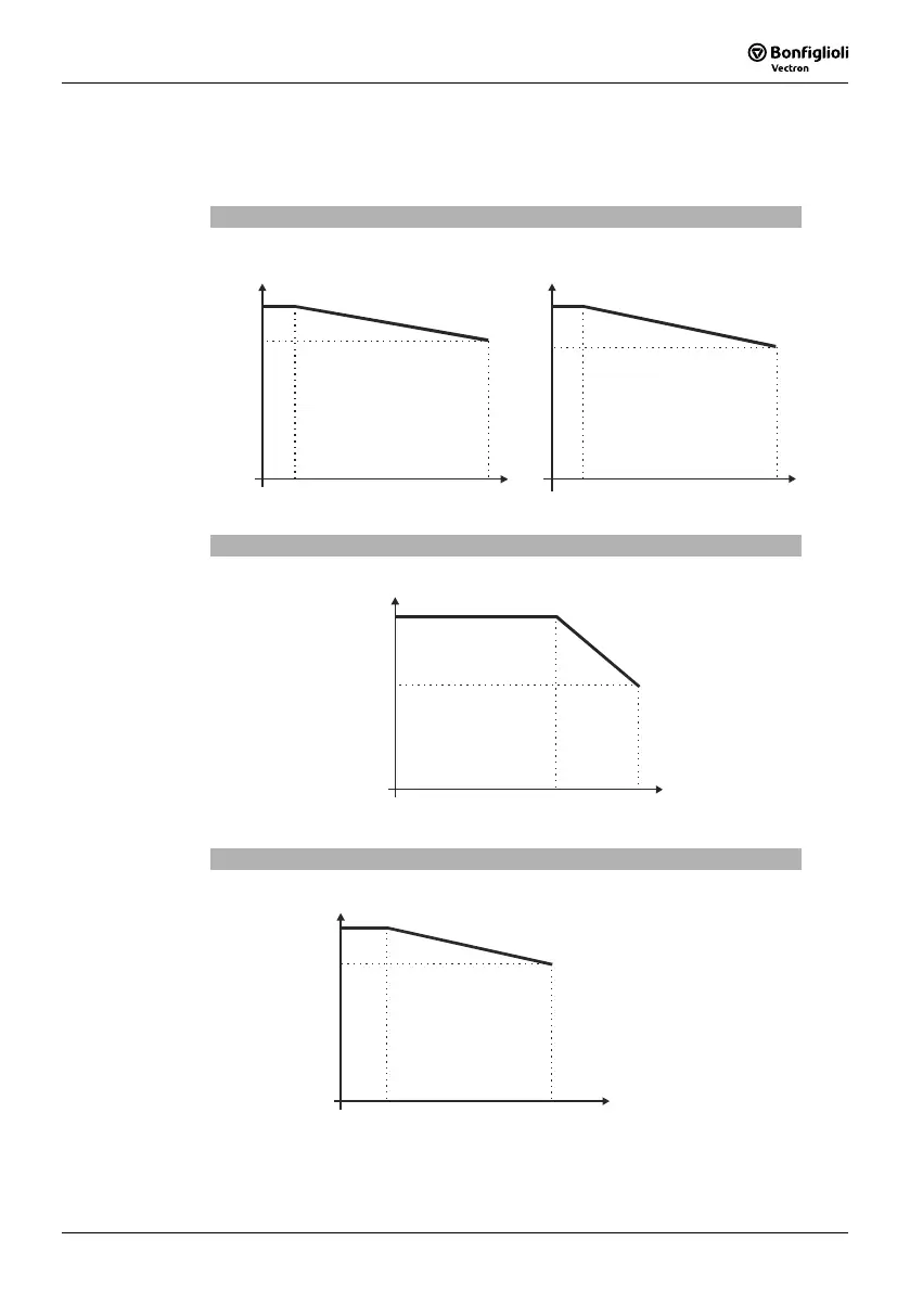
3.10 Operation Diagrams
The technical data of the frequency inverters refer to the nominal point which was
selected to enable a wide range of applications. A functionally and efficient dimension-
ing (de-rating) of the frequency inverters is possible based on the following diagrams.
Site altitude
100
85
60
40
20
55
45
3000
1000
2000 4000
3000
1000
2000
4000
Power reduction (Derating),
5%/1000 m above sea level,
h = 4000 m
max
max. coolant temperature,
3.3 °C/1000 m above sea level,
Mounting altitude in m above sea level Mounting altitude in m above sea level
Output current in %
Coolant temperature in °C
Coolant temperature
100
80
63
40
20
0 10
20
30
40 50 55
Power reduction (Derating)
2.5%/K upper 40 °C, T = 55 °C
max
Output current in
Coolant temperature in °C
Mains voltage
100
83
63
40
20
0 400
420
440
460
480
Output current in %
Mains voltage equal output voltage in V
Reduction of output current at constant output power (Derating
0.22%/ V upper 400 V, U = 480 V
max
 Loading...


