Operating Instructions ACTIVE06/07 135
06/07 Operating Instructions ACTIVE 135
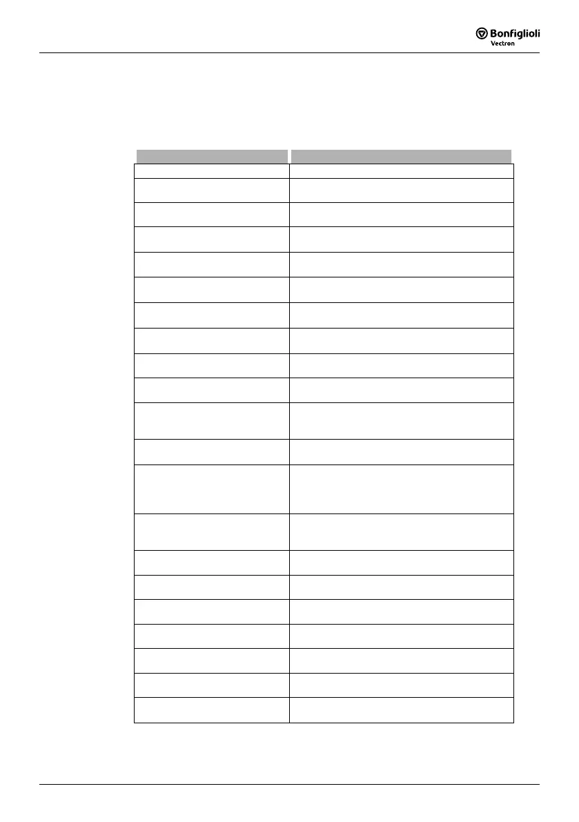
14.3 Digital Outputs
The
OP. Mode Digital Output 1 530 and the relay output with the parameter Op.
Mode Digital Output 3
532 link the digital outputs to various functions. The selection
of the functions depends on the parameterized configuration. The use of the multi-
functional output MFO1 as a digital output demands selection of an
Operation Mode
550 and linking via parameter Digital Operation 554.
Operation mode 530,532,554 Function
0 - Off Digital output is switched off.
1 - Ready or Standby Signal
Frequency inverter is initialized and on stand-by
or in operation.
2 - Run Signal
Controller release signal and a start command are
present, output frequency available.
3 - Error Signal
Message is displayed via the parameter
Current
Error
259 or Warnings 269.
4 - Setting Frequency
The
Stator Frequency 210 is higher than the
parameterized
Setting Frequency 510.
5 -
Reference Frequency
reached
The
Actual Frequency 241 of the drive has
reached the
Internal Reference Frequency 228.
6 -
Reference Percentage
Reached
The
Actual Percentage Value 230 has reached
the
Reference Percentage Value 229.
7 - Ixt warning
The
Warning Limit Short-Term Ixt 405 or Warn-
ing Limit Long-Term Ixt
406 has been reached.
8 -
Warning
Heat sink temperature
Max. heat sink temperature T
K
of 80 °C minus the
Warning Limit Heat Sink Temp. 407 reached.
9 -
Warning
Inside temperature
Max. inside temperature T
i
of 65 °C minus the
Warning Limit Inside Temperature 408 reached.
10 - Warning Motor Temperature
Warning behavior according to parameterized
Motor Temp. Operation Mode 570 at max. motor
temperature T
PTC
.
11 - Warning General
The message is displayed via parameter
Warn-
ings
269.
12 - Warning over temperature
The selected limit values
Warning Limit Heat Sink
Temp. 407,
Warning Limit Inside Temp 408 or
the maximum motor temperature have been ex-
ceeded.
13 - Mains Failure
Failure of the mains voltage and power regulation
active according to
Operation Mode 670 for the
voltage controller.
14 -
Warning Motor Protect.
Switch
Parameterized
Operation Mode 571 for the motor
protection switch has triggered.
15 - Warning Current Limitation
A controller or the
Operation Mode 573 of the
intelligent current limits limit the output current.
16 -
Controller Current Limit.
Long Term Ixt
The overload reserve for 60 s has been used up
and the output current is being limited.
17 -
Controller Current Limit.
Short Term Ixt
The overload reserve for 1 s has been used up
and the output current is being limited.
18 - Controller Current Limit. TK
Max. heat sink temperature TK reached, intelli-
gent current limits of
Operation Mode 573 active.
19 -
Controller Current Limit.
Motor Temp.
Max. motor temperature reached, intelligent cur-
rent limits of
Operation Mode 573 active.
20 - Comparator 1
The comparison according to the selected
OP.
mode
Comparator 1 540 is true.
Table "Operation Modes for Digital Outputs" continued on next page.
 Loading...


