Operating Instructions ACTIVE 06/07132
132 Operating Instructions ACTIVE 06/07
14.1.1.5 Error and warning behavior
For monitoring the analog input signal, an operation mode can be selected via pa-
rameter
Error/Warning Behavior 453.
Error/Warning Behavior 453 Function
0 - Off The input signal is not monitored.
1 - Warning < 1V/2mA
If the input signal is lower than 1 V or 2 mA, a
warning message is issued.
2 - Shut Down < 1V/2mA
If the input signal is lower than 1 V or 2 mA, a
warning message is issued; the drive is deceler-
ated according to stopping behavior 2.
3 -
Error Switch-Off
< 1V/2mA
If the input signal is lower than 1 V or 2 mA, a
warning and fault message is issued and the drive
coasts to a standstill (stopping behavior 0).
Monitoring of the analog input signal is active regardless of the release of the fre-
quency inverter according to the operation mode selected.
Operation mode 2 defines the shut-down and stopping of the drive, regardless of the
setting of parameter
Operation Mode 630 for the stopping behavior. The drive is
stopped according to stopping behavior 2. If the set holding time has expired, an er-
ror message is issued. The drive can be started again by switching the start signal on
and off.
Operation mode 3 defines the free coasting of the drive (like described for stopping
behavior 0), regardless of the setting of parameter
Operation Mode 630 for the stop-
ping behavior.
Attention!
The monitoring of the analog input signal via the parameter
Er-
ror/Warning Behavior
453 demands the examination of the parameter
Point X1 454.
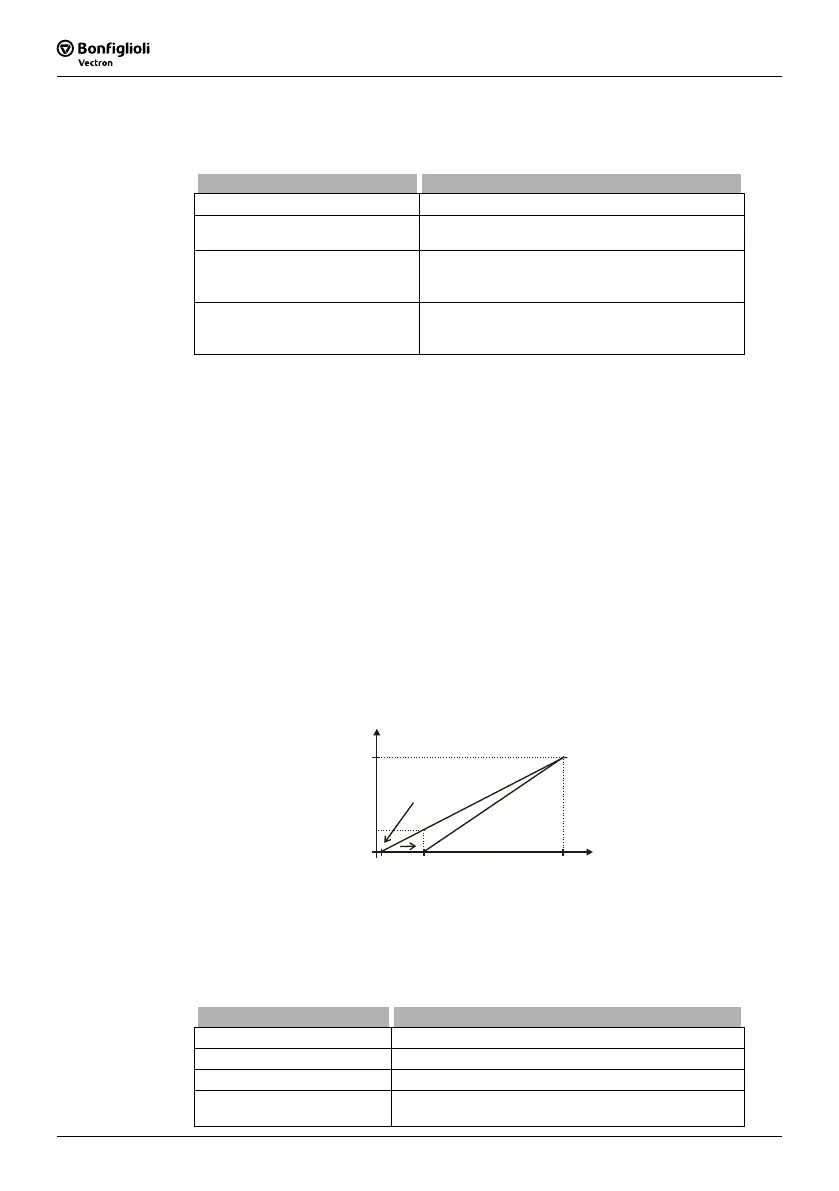
Example: Error/Warning Behavior 453 = “2 - Shut Down < 1V/2mA” or “3 - Error
Switch-Off < 1V/2mA. In the factory setting of parameter
Point X1 454 shut down or
error switch-off is activated at an output frequency unequal to 0 Hz. If shut down or
error switch-off should be activated at an output frequency equal to 0 Hz the parame-
ter
Point X1 454 must be adjusted (e.g. X1=10% /1 V).
50 Hz
9,8 V0,2 V
X
0 Hz
(X1=2% / Y1=0%)
1 V
14.2 Multi-function output MFO1
Multifunction output MFO1 can either be configured as a digital, analog or a repetition
frequency output. Depending on the selected
Operation mode 550 for the multifunc-
tion output, a link to various functions of the software is possible. The operation
modes not used are deactivated internally.
Operation mode 550 Function
0 - Off Output has the logic signal LOW.
1 - Digital Digital output, 0 ... 24 V.
2 - Analog Analog output, 0 ... 24 V.
3 - Repetition frequency
Repetition frequency output, 0 ... 24 V, f
max
= 150
kHz.
 Loading...


