Operating Instructions ACTIVE06/07 27
06/07 Operating Instructions ACTIVE 27
4.2 ACT 201 (4.0 up to 9.2 kW) and ACT 401 (5.5 up to
15.0 kW)
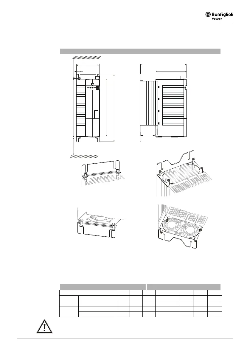
The frequency inverter is mounted in a vertical position on the assembly panel by
means of the standard fittings. The following illustration shows the standard fitting.
Standard installation
b
b1
a
a1 a2
c
x
x
c1
x 100 mm
fixing bracket bottom
(fixing with screws )
M4x60
fixing bracket top
(fixing with screws )
M4x20
Assembly is done by screwing the two fixing brackets to the heat sink of the fre-
quency inverter and the assembly panel.
The frequency inverters are provided with fixing brackets, which are fitted using four
thread-cutting screws.
The dimensions of the device and the installation dimensions are those of the stan-
dard device without optional components and are given in millimeters.
Dimensions in mm Installation dimensions in mm
Frequency inverter
a b c a1 a2 b1 c1
4.0 … 5.5 kW
250 100 200 270 ... 290 315 12 133
ACT 201
7.5 … 9.2 kW
250 125 200 270 ... 290 315 17.5 133
5.5 ... 9.2 kW
250 100 200 270 ... 290 315 12 133
ACT 401
11.0 … 15.0 kW
250 125 200 270 ... 290 315 17.5 133
Caution! Mount the devices with sufficient clearance to other components so that
the cooling air can circulate freely. Avoid soiling by grease and air pollu-
tion by dust, aggressive gases, etc.
 Loading...


